Web cайт посвящён роботу-космонавту ФЕДОРу и „интеллектуалам” ФСБ - это откровенный троллинг. | |||||||||||||||||||||||||||||||||||||||||||||||||||||||||||||||||||||||||||||||||||||||||||||||||||||||||||||||||||||||||||||||||||||||||||||||||||||||||||||||||||||||||||||||||||||||||||||||||||||||||||||||||||||||||||||||||||||||||||||||||||||||||||||||||||||||||||||||||||||||||||||||||||||||||||||||||||||||||||||||||||||||||||||||||||||||||||||||||||||||||||||||||||||||||||||||||||||||||||||||||||||||||||||||||||||||||||||||||||||||||||||||||||||||||||||||||||||||||||||||||||||||||||||||||||||||||||||||||||||||||||||||||||||||||||||||||||||||||||||||||||||||||||||||||||||||||||||||||||||||||||||||||||||||||||||||||||||||||||||||||||||||||||||||||||||||||||||||||||||||||||||||||||||||||||||||||||||||||||||||||||||||||||||||||||||||||||||||||||||||||||||||||||||||||||||||||||||||||||||||||||||||||||||||||||||||||||||||||||||||||||||||||||||||||||||||||||||||||||||||||||||||||||||||||||||||||||||||||||||||||||||||||||||||||||||||||||||||||||||||||||||||||||||||||||||||||||||||||||||||
The method of Streltsov's of compulsory angular orientation of a head and pelvis of the person-operator in the support mechanism, which we uses for remote control a humanoid robot avatar. |
| Способ Стрельцова принудительной угловой ориентации головы и таза человека-оператора в механизме подвеса, применяемого для дистанционного управления антропоморфным роботом-аватаром. | |||||||||||||||||||||||||||||||||||||||||||||||||||||||||||||||||||||||||||||||||||||||||||||||||||||||||||||||||||||||||||||||||||||||||||||||||||||||||||||||||||||||||||||||||||||||||||||||||||||||||||||||||||||||||||||||||||||||||||||||||||||||||||||||||||||||||||||||||||||||||||||||||||||||||||||||||||||||||||||||||||||||||||||||||||||||||||||||||||||||||||||||||||||||||||||||||||||||||||||||||||||||||||||||||||||||||||||||||||||||||||||||||||||||||||||||||||||||||||||||||||||||||||||||||||||||||||||||||||||||||||||||||||||||||||||||||||||||||||||||||||||||||||||||||||||||||||||||||||||||||||||||||||||||||||||||||||||||||||||||||||||||||||||||||||||||||||||||||||||||||||||||||||||||||||||||||||||||||||||||||||||||||||||||||||||||||||||||||||||||||||||||||||||||||||||||||||||||||||||||||||||||||||||||||||||||||||||||||||||||||||||||||||||||||||||||||||||||||||||||||||||||||||||||||||||||||||||||||||||||||||||||||||||||||||||||||||||||||||||||||||||||||||||||||||||||||||||||||||||
| |||||||||||||||||||||||||||||||||||||||||||||||||||||||||||||||||||||||||||||||||||||||||||||||||||||||||||||||||||||||||||||||||||||||||||||||||||||||||||||||||||||||||||||||||||||||||||||||||||||||||||||||||||||||||||||||||||||||||||||||||||||||||||||||||||||||||||||||||||||||||||||||||||||||||||||||||||||||||||||||||||||||||||||||||||||||||||||||||||||||||||||||||||||||||||||||||||||||||||||||||||||||||||||||||||||||||||||||||||||||||||||||||||||||||||||||||||||||||||||||||||||||||||||||||||||||||||||||||||||||||||||||||||||||||||||||||||||||||||||||||||||||||||||||||||||||||||||||||||||||||||||||||||||||||||||||||||||||||||||||||||||||||||||||||||||||||||||||||||||||||||||||||||||||||||||||||||||||||||||||||||||||||||||||||||||||||||||||||||||||||||||||||||||||||||||||||||||||||||||||||||||||||||||||||||||||||||||||||||||||||||||||||||||||||||||||||||||||||||||||||||||||||||||||||||||||||||||||||||||||||||||||||||||||||||||||||||||||||||||||||||||||||||||||||||||||||||||||||||||||
The invention have relation to area of a robotics and can be used, for example, in rescue operations, in the space industry, in a diving business etc. Technical result: increase of quality of management by the anthropomorphous robot avatar. | Изобретение относится к области робототехники и может быть использовано, например, в спасательных операциях, в космической индустрии, в водолазном деле и т.д. Технический результат: повышение качества управления антропоморфным роботом-аватаром. | ||||||||||||||||||||||||||||||||||||||||||||||||||||||||||||||||||||||||||||||||||||||||||||||||||||||||||||||||||||||||||||||||||||||||||||||||||||||||||||||||||||||||||||||||||||||||||||||||||||||||||||||||||||||||||||||||||||||||||||||||||||||||||||||||||||||||||||||||||||||||||||||||||||||||||||||||||||||||||||||||||||||||||||||||||||||||||||||||||||||||||||||||||||||||||||||||||||||||||||||||||||||||||||||||||||||||||||||||||||||||||||||||||||||||||||||||||||||||||||||||||||||||||||||||||||||||||||||||||||||||||||||||||||||||||||||||||||||||||||||||||||||||||||||||||||||||||||||||||||||||||||||||||||||||||||||||||||||||||||||||||||||||||||||||||||||||||||||||||||||||||||||||||||||||||||||||||||||||||||||||||||||||||||||||||||||||||||||||||||||||||||||||||||||||||||||||||||||||||||||||||||||||||||||||||||||||||||||||||||||||||||||||||||||||||||||||||||||||||||||||||||||||||||||||||||||||||||||||||||||||||||||||||||||||||||||||||||||||||||||||||||||||||||||||||||||||||||||||||||||
| |||||||||||||||||||||||||||||||||||||||||||||||||||||||||||||||||||||||||||||||||||||||||||||||||||||||||||||||||||||||||||||||||||||||||||||||||||||||||||||||||||||||||||||||||||||||||||||||||||||||||||||||||||||||||||||||||||||||||||||||||||||||||||||||||||||||||||||||||||||||||||||||||||||||||||||||||||||||||||||||||||||||||||||||||||||||||||||||||||||||||||||||||||||||||||||||||||||||||||||||||||||||||||||||||||||||||||||||||||||||||||||||||||||||||||||||||||||||||||||||||||||||||||||||||||||||||||||||||||||||||||||||||||||||||||||||||||||||||||||||||||||||||||||||||||||||||||||||||||||||||||||||||||||||||||||||||||||||||||||||||||||||||||||||||||||||||||||||||||||||||||||||||||||||||||||||||||||||||||||||||||||||||||||||||||||||||||||||||||||||||||||||||||||||||||||||||||||||||||||||||||||||||||||||||||||||||||||||||||||||||||||||||||||||||||||||||||||||||||||||||||||||||||||||||||||||||||||||||||||||||||||||||||||||||||||||||||||||||||||||||||||||||||||||||||||||||||||||||||||||
Essence of the invention: the data on angular orientations of a head and a pelvis concerning a thorax of the anthropomorphous robot avatar are transferred by a liaison channel to the watching support mechanism, which gives to a head and a pelvis of the person - operator similar angular orientations concerning a thorax of the person - operator, in turn the person - operator, doing force influences by the own head and the pelvis on internal surfaces of a helmet and underpanties, can change of the angular orientations of a head and a pelvis of the robot. | Сущность изобретения: данные об угловых ориентациях головы и таза относительно грудного отдела антропоморфного робота-аватара передаются по каналу связи на следящий механизм подвеса, который придает голове и тазу человека-оператора аналогичные угловые ориентации относительно грудного отдела человека-оператора, в свою очередь человек-оператор оказывая силовые воздействия своей головой и своим тазом на внутренние поверхности шлема и трусов может необходимым образом изменять угловые ориентации головы и таза робота. | ||||||||||||||||||||||||||||||||||||||||||||||||||||||||||||||||||||||||||||||||||||||||||||||||||||||||||||||||||||||||||||||||||||||||||||||||||||||||||||||||||||||||||||||||||||||||||||||||||||||||||||||||||||||||||||||||||||||||||||||||||||||||||||||||||||||||||||||||||||||||||||||||||||||||||||||||||||||||||||||||||||||||||||||||||||||||||||||||||||||||||||||||||||||||||||||||||||||||||||||||||||||||||||||||||||||||||||||||||||||||||||||||||||||||||||||||||||||||||||||||||||||||||||||||||||||||||||||||||||||||||||||||||||||||||||||||||||||||||||||||||||||||||||||||||||||||||||||||||||||||||||||||||||||||||||||||||||||||||||||||||||||||||||||||||||||||||||||||||||||||||||||||||||||||||||||||||||||||||||||||||||||||||||||||||||||||||||||||||||||||||||||||||||||||||||||||||||||||||||||||||||||||||||||||||||||||||||||||||||||||||||||||||||||||||||||||||||||||||||||||||||||||||||||||||||||||||||||||||||||||||||||||||||||||||||||||||||||||||||||||||||||||||||||||||||||||||||||||||||||
Below I insert of the drawing-"roentgenogram", which is showing to us of the elaborate kinematics of bones of a neck of the person at various movements of a head: | Ниже приведен рисунок-"рентгенограмма", показывающий сложную кинематику костей шеи человека при различных движениях головы: | ||||||||||||||||||||||||||||||||||||||||||||||||||||||||||||||||||||||||||||||||||||||||||||||||||||||||||||||||||||||||||||||||||||||||||||||||||||||||||||||||||||||||||||||||||||||||||||||||||||||||||||||||||||||||||||||||||||||||||||||||||||||||||||||||||||||||||||||||||||||||||||||||||||||||||||||||||||||||||||||||||||||||||||||||||||||||||||||||||||||||||||||||||||||||||||||||||||||||||||||||||||||||||||||||||||||||||||||||||||||||||||||||||||||||||||||||||||||||||||||||||||||||||||||||||||||||||||||||||||||||||||||||||||||||||||||||||||||||||||||||||||||||||||||||||||||||||||||||||||||||||||||||||||||||||||||||||||||||||||||||||||||||||||||||||||||||||||||||||||||||||||||||||||||||||||||||||||||||||||||||||||||||||||||||||||||||||||||||||||||||||||||||||||||||||||||||||||||||||||||||||||||||||||||||||||||||||||||||||||||||||||||||||||||||||||||||||||||||||||||||||||||||||||||||||||||||||||||||||||||||||||||||||||||||||||||||||||||||||||||||||||||||||||||||||||||||||||||||||||||
The skeleton of the person is below shown, the spine and a neck I outline round by a red marker. | |||||||||||||||||||||||||||||||||||||||||||||||||||||||||||||||||||||||||||||||||||||||||||||||||||||||||||||||||||||||||||||||||||||||||||||||||||||||||||||||||||||||||||||||||||||||||||||||||||||||||||||||||||||||||||||||||||||||||||||||||||||||||||||||||||||||||||||||||||||||||||||||||||||||||||||||||||||||||||||||||||||||||||||||||||||||||||||||||||||||||||||||||||||||||||||||||||||||||||||||||||||||||||||||||||||||||||||||||||||||||||||||||||||||||||||||||||||||||||||||||||||||||||||||||||||||||||||||||||||||||||||||||||||||||||||||||||||||||||||||||||||||||||||||||||||||||||||||||||||||||||||||||||||||||||||||||||||||||||||||||||||||||||||||||||||||||||||||||||||||||||||||||||||||||||||||||||||||||||||||||||||||||||||||||||||||||||||||||||||||||||||||||||||||||||||||||||||||||||||||||||||||||||||||||||||||||||||||||||||||||||||||||||||||||||||||||||||||||||||||||||||||||||||||||||||||||||||||||||||||||||||||||||||||||||||||||||||||||||||||||||||||||||||||||||||||||||||||||||||||
However, manufacturers of anthropomorphic robots are unlikely to consider it possible to massively use in the manufacture of their products mechanical joints with absolutely the same complex kinematics and complex control systems as in the human body (a large number of degrees of freedom in mechanics and control of matched signals). Therefore it is expedient to consider other more simple kinematics schemes for creation the anthropomorphous robots, for providing titling and turns of a head and a pelvis of the robot concerning a thorax (torso) of the robot. The conditional kinematics scheme of joints of a neck of the robot (a skeleton of a neck department of the anthropomorphous robot) is submitted on a drawing # 3. (For obviousness: Near of the kinematics scheme of the robot I show of the movable image of a skeleton of the person <on the right> - where red color indicate a site of a skeleton of the person, which corresponds of the kinematics scheme of the robot) | Однако изготовители антропоморфных роботов едва ли сочтут возможным массово применять при изготовлении своей продукции механические сочленения с абсолютно такой же сложной кинематикой и сложной системой управления как в человеческом теле (большое число степеней свободы по механике и по управляющим согласованным сигналам). Поэтому целесообразно рассмотреть другие более простые кинематические схемы для создания антропоморфных роботов, обеспечивающие наклоны и повороты головы и таза робота относительно грудной клетки (торса) робота. Условная кинематическая схема суставов шеи робота (скелет шейного отдела антропоморфного робота) представлена на фигуре № 3. (Рядом с кинематической схемой робота для наглядности приводится <справа> подвижное изображение скелета человека - красным цветом выделен участок скелета человека, которому соответствует кинематическая схема робота) | ||||||||||||||||||||||||||||||||||||||||||||||||||||||||||||||||||||||||||||||||||||||||||||||||||||||||||||||||||||||||||||||||||||||||||||||||||||||||||||||||||||||||||||||||||||||||||||||||||||||||||||||||||||||||||||||||||||||||||||||||||||||||||||||||||||||||||||||||||||||||||||||||||||||||||||||||||||||||||||||||||||||||||||||||||||||||||||||||||||||||||||||||||||||||||||||||||||||||||||||||||||||||||||||||||||||||||||||||||||||||||||||||||||||||||||||||||||||||||||||||||||||||||||||||||||||||||||||||||||||||||||||||||||||||||||||||||||||||||||||||||||||||||||||||||||||||||||||||||||||||||||||||||||||||||||||||||||||||||||||||||||||||||||||||||||||||||||||||||||||||||||||||||||||||||||||||||||||||||||||||||||||||||||||||||||||||||||||||||||||||||||||||||||||||||||||||||||||||||||||||||||||||||||||||||||||||||||||||||||||||||||||||||||||||||||||||||||||||||||||||||||||||||||||||||||||||||||||||||||||||||||||||||||||||||||||||||||||||||||||||||||||||||||||||||||||||||||||||||||||
The neck of the robot is submitted by axes of rotation with symbols designations D, C, F; G - later mathematical calculations with the corners having the similar e symbols designations will be submitted. Some lines on drawing, representing rigid elements of a skeleton of a neck of the robot, in places of crossing have a thickening - by it is designated a moment, what such lines have of a real crossing in space in the given place and have rigid connection, and on the contrary, lines, which on drawing at a crossing not have of a thickening, are not crossed in space. The "Triangle", designated by symbols R-L-N, is a torso (a thorax) of robot (R - a Right shoulder, L - a Left shoulder, N - a Navel, a stomach). The kinematic pairs the first order: D (located in the basis of a neck of the robot) and C (located in the basis of a skull of the robot) provide tiltings «forward - back» heads of the robot - these tiltings correspond to tiltings «forward - back» heads of the person, as represented on a drawing # 2. The axis F have location in the basis of a skull of the robot crosswisely to axis C, allowing the robot to tilt its head from side to side in the direction of the left or right shoulders - shake its head. (On a drawing # 3 I conditionally show of head of the robot, his face, above a crossing of axes C, F, G, but in a reality the point of crossing of these axes will be inside a head of the robot - in the basis of his skull.) For the person such movements - rotations around of axis F have look as tiltings of a head aside to the left - to right shoulders how it is shown on a drawing # 4. | Шея робота представлена осями вращения с буквенными обозначениями D, C, F; G – позже будут представлены математические выкладки с углами, имеющими такие же буквенные обозначения. Некоторые линии, изображающие жесткие элементы скелета шеи робота, в местах пересечения имеют утолщение – этим обозначается, что пересекающиеся линии имеют в пространстве в данном месте жесткое соединение, и напротив, линии, при пересечении которых утолщения нет, не пересекаются в пространстве. «Треугольник», обозначенный буквами R-L-N, - это торс (грудной отдел) робота (R - правое плечё, L - левое плечё, N - пупок (Navel), живот). Кинематические пары первого порядка: D (расположенная в основании шеи робота) и C (расположенная в основании черепа робота) обеспечивают наклоны «вперед – назад» головы робота – эти наклоны соответствуют наклонам «вперед – назад» головы человека, изображенным на фигуре № 2. Крестообразно к оси C в основании черепа робота располагается ось F позволяющая роботу наклонять голову из стороны в сторону в направлении левого или правого плеч - покачивать головой. (На фигуре № 3 голова робота, лицо, условно показана выше пересечения осей C, F, G на деле же точка пересечения этих осей будет находиться внутри головы робота - в основании его черепа.) Для человека такие движения-повороты вокруг оси F выглядят как наклоны головы влево - вправо в сторону плеч, так, как это показано на фигуре № 4. | ||||||||||||||||||||||||||||||||||||||||||||||||||||||||||||||||||||||||||||||||||||||||||||||||||||||||||||||||||||||||||||||||||||||||||||||||||||||||||||||||||||||||||||||||||||||||||||||||||||||||||||||||||||||||||||||||||||||||||||||||||||||||||||||||||||||||||||||||||||||||||||||||||||||||||||||||||||||||||||||||||||||||||||||||||||||||||||||||||||||||||||||||||||||||||||||||||||||||||||||||||||||||||||||||||||||||||||||||||||||||||||||||||||||||||||||||||||||||||||||||||||||||||||||||||||||||||||||||||||||||||||||||||||||||||||||||||||||||||||||||||||||||||||||||||||||||||||||||||||||||||||||||||||||||||||||||||||||||||||||||||||||||||||||||||||||||||||||||||||||||||||||||||||||||||||||||||||||||||||||||||||||||||||||||||||||||||||||||||||||||||||||||||||||||||||||||||||||||||||||||||||||||||||||||||||||||||||||||||||||||||||||||||||||||||||||||||||||||||||||||||||||||||||||||||||||||||||||||||||||||||||||||||||||||||||||||||||||||||||||||||||||||||||||||||||||||||||||||||||||
For an anthropomorphic robot controlled in copying mode, it will be possible to get by with one joint in the base of the robot's skull One more axis of rotation G is a perpendicular to axes C and F, she provides turns of a head of the robot on the left - to the right. | Для антропоморфного робота, управляемого в копирующем режиме можно будет обойтись одним суставом в основании черепа робота Ещё одна ось G вращения, перпендикулярная осям C и F, обеспечивает повороты головы робота налево–направо. | ||||||||||||||||||||||||||||||||||||||||||||||||||||||||||||||||||||||||||||||||||||||||||||||||||||||||||||||||||||||||||||||||||||||||||||||||||||||||||||||||||||||||||||||||||||||||||||||||||||||||||||||||||||||||||||||||||||||||||||||||||||||||||||||||||||||||||||||||||||||||||||||||||||||||||||||||||||||||||||||||||||||||||||||||||||||||||||||||||||||||||||||||||||||||||||||||||||||||||||||||||||||||||||||||||||||||||||||||||||||||||||||||||||||||||||||||||||||||||||||||||||||||||||||||||||||||||||||||||||||||||||||||||||||||||||||||||||||||||||||||||||||||||||||||||||||||||||||||||||||||||||||||||||||||||||||||||||||||||||||||||||||||||||||||||||||||||||||||||||||||||||||||||||||||||||||||||||||||||||||||||||||||||||||||||||||||||||||||||||||||||||||||||||||||||||||||||||||||||||||||||||||||||||||||||||||||||||||||||||||||||||||||||||||||||||||||||||||||||||||||||||||||||||||||||||||||||||||||||||||||||||||||||||||||||||||||||||||||||||||||||||||||||||||||||||||||||||||||||||||
Because here is discussed the question of creation of the anthropomorphous robot, which repeating (copying) movements of the person - operator, and a question of creation of the control by this robot by means of a costume, heads of the person "on the left - on the right" in a direction of shoulders can are made in a range approximately ± 450 - this nuance is displayed on a drawing # 5. The attempts to exceed in managing costume The note: Some people, having natural unique talent and persistently training, develop extremely big flexibility of a own body - for example: they can rotate a head on considerably big angles than the majority of people, and below also I show of photos of a very flexible actress: | Т.к. здесь обсуждается вопрос создания антропоморфного робота, повторяющего (копирующего) движения человека-оператора, и вопрос создания управляющего этим роботом костюма,головы человека 0 – этот нюанс отображен на фигуре № 5. Попытки превысить в управляющем костюме Примечание: Некоторые люди, обладая природным даром и упорно тренируясь, развивают чрезвычайно большую гибкость тела - например: они могут поворачивать голову на значительно большие углы чем большинство людей, а ниже показаны фотографии очень гибкой гимнастки: | ||||||||||||||||||||||||||||||||||||||||||||||||||||||||||||||||||||||||||||||||||||||||||||||||||||||||||||||||||||||||||||||||||||||||||||||||||||||||||||||||||||||||||||||||||||||||||||||||||||||||||||||||||||||||||||||||||||||||||||||||||||||||||||||||||||||||||||||||||||||||||||||||||||||||||||||||||||||||||||||||||||||||||||||||||||||||||||||||||||||||||||||||||||||||||||||||||||||||||||||||||||||||||||||||||||||||||||||||||||||||||||||||||||||||||||||||||||||||||||||||||||||||||||||||||||||||||||||||||||||||||||||||||||||||||||||||||||||||||||||||||||||||||||||||||||||||||||||||||||||||||||||||||||||||||||||||||||||||||||||||||||||||||||||||||||||||||||||||||||||||||||||||||||||||||||||||||||||||||||||||||||||||||||||||||||||||||||||||||||||||||||||||||||||||||||||||||||||||||||||||||||||||||||||||||||||||||||||||||||||||||||||||||||||||||||||||||||||||||||||||||||||||||||||||||||||||||||||||||||||||||||||||||||||||||||||||||||||||||||||||||||||||||||||||||||||||||||||||||||||
The amazing result!… Looking at these photos, I even distantly do not represent a design of a exoskeleton and the support mechanism for this actress. However in the support mechanism we shall be compelled to be guided by flexibility of the average statistical person or even of a elderly person, at which a mobility of joints is appreciably less. Our task is more modest - to provide to the average statistical person-operator operating the robot, mobility (flexibility of joints), comparable with a work in a semi-rigid survival suit or in a medieval armour. As a result of it we will get of the remote control anthropomorphous robot avatars, which will have a plasticity of the average person, what is quite enough for remote execution of a various sort of industrial works and of a rescues operations. Any extraordinary flexibility is not stipulated in the exoskeleton and in a support mechanism. Thus, because of human anatomy similar average restrictions on amplitudes of turns of joints will be observed and at the anthropomorphous robot repeating movements of the person-operator.
(For completely INDEPENDENT anthropomorphous the robot with an artificial intellect of such restrictions is not present - for such independent robot the situation of turns of a head and other finitenesses on any angle basically is possible - you can look at this account of a fight of two terminators, the adventures of Gummi bears and others. | Поразительный результат!… Глядя на эти фотографии, я даже отдалённо не представляю конструкцию экозскелета и механизма подвеса для этой артистки. Однако мы в экзоскелете и в механизме подвеса будем вынуждены ориентироваться на гибкость среднестатистического человека или даже пожилого человека, у которых подвижность суставов существенно меньше. Наша задача скромней - обеспечить среднестатистическому человеку-оператору, управляющему роботом, мобильность (гибкость суставов), сопоставимую с работой в полужестком скафандре или в средневековых латах. В результате этого получится дистанционно управляемый антропоморфный робот-аватар, обладающий пластикой среднестатистического человека, что вполне достаточно для дистанционного выполнения различного рода промышленных работ и спасательных операций. Никакой экстраординарной гибкости в экзоскелете и механизме подвеса не предусмотрено. Таким образом, из-за анатомии человека аналогичные среднестатистические ограничения по амплитудам поворотов суставов будут наблюдаться и у антропоморфного робота, повторяющего движения человека-оператора. (Для полностью АВТОНОМНОГО антропоморфного робота с искусственным интеллектом таких ограничений нет - для такого автономного робота в принципе возможна ситуация поворотов головы и других конечностей на любой угол - смотрите на этот счёт битву терминаторов, приключения мишек Гамми и др.: | ||||||||||||||||||||||||||||||||||||||||||||||||||||||||||||||||||||||||||||||||||||||||||||||||||||||||||||||||||||||||||||||||||||||||||||||||||||||||||||||||||||||||||||||||||||||||||||||||||||||||||||||||||||||||||||||||||||||||||||||||||||||||||||||||||||||||||||||||||||||||||||||||||||||||||||||||||||||||||||||||||||||||||||||||||||||||||||||||||||||||||||||||||||||||||||||||||||||||||||||||||||||||||||||||||||||||||||||||||||||||||||||||||||||||||||||||||||||||||||||||||||||||||||||||||||||||||||||||||||||||||||||||||||||||||||||||||||||||||||||||||||||||||||||||||||||||||||||||||||||||||||||||||||||||||||||||||||||||||||||||||||||||||||||||||||||||||||||||||||||||||||||||||||||||||||||||||||||||||||||||||||||||||||||||||||||||||||||||||||||||||||||||||||||||||||||||||||||||||||||||||||||||||||||||||||||||||||||||||||||||||||||||||||||||||||||||||||||||||||||||||||||||||||||||||||||||||||||||||||||||||||||||||||||||||||||||||||||||||||||||||||||||||||||||||||||||||||||||||||||
| |||||||||||||||||||||||||||||||||||||||||||||||||||||||||||||||||||||||||||||||||||||||||||||||||||||||||||||||||||||||||||||||||||||||||||||||||||||||||||||||||||||||||||||||||||||||||||||||||||||||||||||||||||||||||||||||||||||||||||||||||||||||||||||||||||||||||||||||||||||||||||||||||||||||||||||||||||||||||||||||||||||||||||||||||||||||||||||||||||||||||||||||||||||||||||||||||||||||||||||||||||||||||||||||||||||||||||||||||||||||||||||||||||||||||||||||||||||||||||||||||||||||||||||||||||||||||||||||||||||||||||||||||||||||||||||||||||||||||||||||||||||||||||||||||||||||||||||||||||||||||||||||||||||||||||||||||||||||||||||||||||||||||||||||||||||||||||||||||||||||||||||||||||||||||||||||||||||||||||||||||||||||||||||||||||||||||||||||||||||||||||||||||||||||||||||||||||||||||||||||||||||||||||||||||||||||||||||||||||||||||||||||||||||||||||||||||||||||||||||||||||||||||||||||||||||||||||||||||||||||||||||||||||||||||||||||||||||||||||||||||||||||||||||||||||||||||||||||||||||||
| |||||||||||||||||||||||||||||||||||||||||||||||||||||||||||||||||||||||||||||||||||||||||||||||||||||||||||||||||||||||||||||||||||||||||||||||||||||||||||||||||||||||||||||||||||||||||||||||||||||||||||||||||||||||||||||||||||||||||||||||||||||||||||||||||||||||||||||||||||||||||||||||||||||||||||||||||||||||||||||||||||||||||||||||||||||||||||||||||||||||||||||||||||||||||||||||||||||||||||||||||||||||||||||||||||||||||||||||||||||||||||||||||||||||||||||||||||||||||||||||||||||||||||||||||||||||||||||||||||||||||||||||||||||||||||||||||||||||||||||||||||||||||||||||||||||||||||||||||||||||||||||||||||||||||||||||||||||||||||||||||||||||||||||||||||||||||||||||||||||||||||||||||||||||||||||||||||||||||||||||||||||||||||||||||||||||||||||||||||||||||||||||||||||||||||||||||||||||||||||||||||||||||||||||||||||||||||||||||||||||||||||||||||||||||||||||||||||||||||||||||||||||||||||||||||||||||||||||||||||||||||||||||||||||||||||||||||||||||||||||||||||||||||||||||||||||||||||||||||||||
But for a distantly controlled anthropomorphous robot, which executing copying movements of the person, restriction of movements in amplitude are necessary.) The waist: | Но для дистанционно управляемого антропоморфного робота, копирующего движения человека, ограничения движений по амплитуде необходимы.) Поясница: | ||||||||||||||||||||||||||||||||||||||||||||||||||||||||||||||||||||||||||||||||||||||||||||||||||||||||||||||||||||||||||||||||||||||||||||||||||||||||||||||||||||||||||||||||||||||||||||||||||||||||||||||||||||||||||||||||||||||||||||||||||||||||||||||||||||||||||||||||||||||||||||||||||||||||||||||||||||||||||||||||||||||||||||||||||||||||||||||||||||||||||||||||||||||||||||||||||||||||||||||||||||||||||||||||||||||||||||||||||||||||||||||||||||||||||||||||||||||||||||||||||||||||||||||||||||||||||||||||||||||||||||||||||||||||||||||||||||||||||||||||||||||||||||||||||||||||||||||||||||||||||||||||||||||||||||||||||||||||||||||||||||||||||||||||||||||||||||||||||||||||||||||||||||||||||||||||||||||||||||||||||||||||||||||||||||||||||||||||||||||||||||||||||||||||||||||||||||||||||||||||||||||||||||||||||||||||||||||||||||||||||||||||||||||||||||||||||||||||||||||||||||||||||||||||||||||||||||||||||||||||||||||||||||||||||||||||||||||||||||||||||||||||||||||||||||||||||||||||||||||
The line, which marked by symbols R-L, - is a pelvis of the robot, or, more precisely, it is a line of fastening of legs of the robot, hip femoral joints of the robot, to a pelvis) . Torso N of the anthropomorphous robot can make turns "on the left - to the right" concerning a pelvis around of a vertical line by means of axis G. Turns of details around of axes D and C give for the robot an opportunity to bend down forward - back. The turns around of axis F give to the robot an opportunity to incline torso to the left - to the right concerning pelvis - for a person such movements are shown on a drawing # 7. | Линия, отмеченная буквами R-L, - таз робота, точнее это линия крепления ног робота, бедренных суставов робота, к тазу). Торс N антропоморфного робота может совершать повороты «налево-направо» относительно таза вокруг вертикальной линии за счет поворота оси G. Повороты деталей вокруг осей D и C обеспечивают роботу возможность нагибаться вперед-назад. Повороты вокруг оси F обеспечивают роботу возможность наклонять торс влево - вправо относительно таза – для человека такие движения показаны на фигуре № 7. | ||||||||||||||||||||||||||||||||||||||||||||||||||||||||||||||||||||||||||||||||||||||||||||||||||||||||||||||||||||||||||||||||||||||||||||||||||||||||||||||||||||||||||||||||||||||||||||||||||||||||||||||||||||||||||||||||||||||||||||||||||||||||||||||||||||||||||||||||||||||||||||||||||||||||||||||||||||||||||||||||||||||||||||||||||||||||||||||||||||||||||||||||||||||||||||||||||||||||||||||||||||||||||||||||||||||||||||||||||||||||||||||||||||||||||||||||||||||||||||||||||||||||||||||||||||||||||||||||||||||||||||||||||||||||||||||||||||||||||||||||||||||||||||||||||||||||||||||||||||||||||||||||||||||||||||||||||||||||||||||||||||||||||||||||||||||||||||||||||||||||||||||||||||||||||||||||||||||||||||||||||||||||||||||||||||||||||||||||||||||||||||||||||||||||||||||||||||||||||||||||||||||||||||||||||||||||||||||||||||||||||||||||||||||||||||||||||||||||||||||||||||||||||||||||||||||||||||||||||||||||||||||||||||||||||||||||||||||||||||||||||||||||||||||||||||||||||||||||||||||
In principle nothing extraordinary in the similar device of a neck or a lumbar department of the anthropomorphous robot not. In present time is important another: what we can try to reproduce similar kinematics schemas of axes of rotation and in the support mechanism, used for management by the anthropomorphous robot. However we should take care thus of, that axes of rotation of a mechanisms management (the manager exoskeleton), which put on on the person, in a reality would not pierce a body of the person - operator managing the robot. Only geometrical continuations of axes (virtual axes) of the external mechanisms environmental of the person - operator can conditionally "pierce" a body of the person - operator. Exosceleton, put on on the person - operator for management by the robot, conditionally we shall share into three parts. The first part: “vest” is a rigid structure, shaped like a T-shirt or vest, covering the chest area of the human operator’s body, with mobile mechanisms attached to it, which covering the upper limbs (hands) of the human operator, so that the person can move his hands and thanks to this, remotely control the manipulators of the robot in copying mode, as well as receive power and tactile sensations from the robot via communication channels. In the patent specification for the invention # 2134193 ru there is an appropriate drawing (# 85) with the image of the shaded waistcoat and an internal ring of the support mechanism. This image from the patent # 2134193 is required to us now for the further logic constructions, therefore I reproduce this image here as a drawing # 8. | В принципе в подобном устройстве шеи или спинного поясничного отдела антропоморфного робота нет ничего экстраординарного. Важно другое, что мы можем попытаться воспроизвести аналогичные кинематические схемы осей вращения и в механизме подвеса, применяемого для управления антропоморфным роботом. Однако нам придется при этом позаботиться о том, чтобы оси вращения механизмов управлении (управляющего экзоскелета), надеваемых на человека, в реальности не протыкали бы тело человека-оператора, управляющего роботом. Тело человека-оператора могут «протыкать» только геометрические продолжения осей (виртуальные оси) внешних механизмов, окружающих человека-оператора. Экзоскелет, надеваемый на человека-оператора для управления роботом, условно разделим на три части. Первая часть: «жилет» - жесткая конструкция, по форме напоминающая майку или жилет, охватывающая грудную область тела человека-оператора, с закрепленными на ней подвижными механизмами, покрывающими верхние конечности (руки) человека-оператора, таким образом, что человек может двигать своими руками и благодаря этому дистанционно управлять в копирующем режиме манипуляторами робота, а также получать от робота по каналам связи силовые и тактильные ощущения. В описании патента на изобретение № 2134193 ru имеется соответствующая фигура (№ 85) с изображением заштрихованного жилета и внутреннего кольца механизма подвеса. Это изображение из патента № 2134193 нам понадобится для дальнейших логических построений, поэтому я это изображение воспроизвожу в качестве фигуры № 8. | ||||||||||||||||||||||||||||||||||||||||||||||||||||||||||||||||||||||||||||||||||||||||||||||||||||||||||||||||||||||||||||||||||||||||||||||||||||||||||||||||||||||||||||||||||||||||||||||||||||||||||||||||||||||||||||||||||||||||||||||||||||||||||||||||||||||||||||||||||||||||||||||||||||||||||||||||||||||||||||||||||||||||||||||||||||||||||||||||||||||||||||||||||||||||||||||||||||||||||||||||||||||||||||||||||||||||||||||||||||||||||||||||||||||||||||||||||||||||||||||||||||||||||||||||||||||||||||||||||||||||||||||||||||||||||||||||||||||||||||||||||||||||||||||||||||||||||||||||||||||||||||||||||||||||||||||||||||||||||||||||||||||||||||||||||||||||||||||||||||||||||||||||||||||||||||||||||||||||||||||||||||||||||||||||||||||||||||||||||||||||||||||||||||||||||||||||||||||||||||||||||||||||||||||||||||||||||||||||||||||||||||||||||||||||||||||||||||||||||||||||||||||||||||||||||||||||||||||||||||||||||||||||||||||||||||||||||||||||||||||||||||||||||||||||||||||||||||||||||||||
| |||||||||||||||||||||||||||||||||||||||||||||||||||||||||||||||||||||||||||||||||||||||||||||||||||||||||||||||||||||||||||||||||||||||||||||||||||||||||||||||||||||||||||||||||||||||||||||||||||||||||||||||||||||||||||||||||||||||||||||||||||||||||||||||||||||||||||||||||||||||||||||||||||||||||||||||||||||||||||||||||||||||||||||||||||||||||||||||||||||||||||||||||||||||||||||||||||||||||||||||||||||||||||||||||||||||||||||||||||||||||||||||||||||||||||||||||||||||||||||||||||||||||||||||||||||||||||||||||||||||||||||||||||||||||||||||||||||||||||||||||||||||||||||||||||||||||||||||||||||||||||||||||||||||||||||||||||||||||||||||||||||||||||||||||||||||||||||||||||||||||||||||||||||||||||||||||||||||||||||||||||||||||||||||||||||||||||||||||||||||||||||||||||||||||||||||||||||||||||||||||||||||||||||||||||||||||||||||||||||||||||||||||||||||||||||||||||||||||||||||||||||||||||||||||||||||||||||||||||||||||||||||||||||||||||||||||||||||||||||||||||||||||||||||||||||||||||||||||||||||
The second part of exoskeleton: "helmet" - a headgear which is put on on a head of the person - operator, with devices of display visual and the audioinformation received from the robot by liaison channels, a radio intercom, …, with an opportunity to operate movements of a head of the robot and feedback by a force (tactile) from the robot on a head of the person - operator. And the third part of an exoskeleton is: "trousers" - the mechanisms covering of the bottom part of a body of the person - operator - the pelvis area and the bottom finitenesses (legs) with an opportunity to operate movements of the bottom finitenesses (pediculators) of the anthropomorphous robot and to receive from the bottom finitenesses of the robot of a force (tactile) sensations. In present our primary goal: the second and a third of a parts of an exoskeleton (a helmet and trousers) to attach movably to the support mechanism with an opportunity of compulsory their movements concerning a thorax (concerning a waistcoat). At present time the experts at development of a distantly controlled anthropomorphous robots do not give due attention to a question of management of a head of robots, and also the bottom part of a body (pelvis) of the robot. (Besides it, the majority of researchers, apparently, have no correct notion about designing of a force exoskeletons.) Usually an experts suggest putting on the head of a human operator, controlling a robot, simple virtual reality spectacles, showing the operator a visual image from the cameras-eyes of the robot. Experts think, that the person - operator, turning the head, can turn and a head of the robot - you can see of the photos below where we see simple spectacles of a virtual reality on heads of people - operators, and in some cases absence of management of a pelvis - operators sit on chairs, operating only the top part of a body of the robot: | Вторая часть экзоскелета: «шлем» - головной убор, надеваемый на голову человека-оператора, с устройствами отображения визуальной и аудиоинформации, получаемой от робота по каналам связи, радиопереговорным устройством,…, с возможностью управлять движениями головы робота и обратной силовой (тактильной) связью от робота на голову человека-оператора. И третья часть экзоскелета: «брюки» - механизмы, покрывающие нижнюю часть тела человека-оператора - тазовую область и нижние конечности (ноги) с возможностью управлять движениями нижних конечностей (педикуляторов) антропоморфного робота и получать от нижних конечностей робота силовые (тактильные) ощущения. Наша основная задача: вторую и третью части экзоскелата (шлем и брюки) прикрепить подвижно к механизму подвеса с возможностью принудительных движений их относительно грудного отдела (относительно жилета). В данное время специалисты при разработке дистанционно управляемых антропоморфных роботов не уделяют должного внимания вопросу управления головой роботов, а также нижней части тела (таза) робота. (Кроме того, большинство исследователей, по-видимому, не имеют правильного представления о конструировании силовых экзоскелетов.) Специалисты предлагают надевать на голову человека-оператора, управляющего роботом, простые очки виртуальной реальности, демонстрирующее оператору визуальное изображение с камер-глаз робота. Специалисты предполагают, что человек-оператор, поворачивая свою голову, может поворачивать и голову робота - смотрите фигуры ниже, где мы видим на головах людей-операторов простые очки виртуальной реальности, и в ряде случаев отсутствие управление тазом - операторы сидят на стульях, управляя только верхней частью тела робота: | ||||||||||||||||||||||||||||||||||||||||||||||||||||||||||||||||||||||||||||||||||||||||||||||||||||||||||||||||||||||||||||||||||||||||||||||||||||||||||||||||||||||||||||||||||||||||||||||||||||||||||||||||||||||||||||||||||||||||||||||||||||||||||||||||||||||||||||||||||||||||||||||||||||||||||||||||||||||||||||||||||||||||||||||||||||||||||||||||||||||||||||||||||||||||||||||||||||||||||||||||||||||||||||||||||||||||||||||||||||||||||||||||||||||||||||||||||||||||||||||||||||||||||||||||||||||||||||||||||||||||||||||||||||||||||||||||||||||||||||||||||||||||||||||||||||||||||||||||||||||||||||||||||||||||||||||||||||||||||||||||||||||||||||||||||||||||||||||||||||||||||||||||||||||||||||||||||||||||||||||||||||||||||||||||||||||||||||||||||||||||||||||||||||||||||||||||||||||||||||||||||||||||||||||||||||||||||||||||||||||||||||||||||||||||||||||||||||||||||||||||||||||||||||||||||||||||||||||||||||||||||||||||||||||||||||||||||||||||||||||||||||||||||||||||||||||||||||||||||||||
However defect such simple (without feedback by a force from the robot to the person ) control systems of a head of the robot is so, that the external forces influences rendered on a head of the robot, are not transferred to a head of the person - operator. Thus situations are possible when external force influences are tilting or turn a head of the robot while the head of the person - operator be in former position - it causes discrepancy of the videoimage received by the person - operator and can entail mistakes in management by a robot. For example, the head of the person - operator managing the robot, have a turn to the right, but the head of the robot under influence of external force influences have turn to the left, thus the person - operator wrongly can think, that the image, observably by him, is on the right from the robot, but in actually it is on the left yet. Besides, the power effects on the head of the human operator are necessary for unloading the muscles of the human neck. As an example, demonstrating this situation can be considered long time work of the robot in a horizontal position-here are the drawings № 76 and № 75 from the description of the patent for the invention # 2134193 Ru. Let's say that the working environment requires a long time horizontal position of the robot, you can look of a drawing № 9. | Однако недостаток таких простых (без обратной силовой связи от робота к человеку) систем управления головой робота состоит в том, что внешние силовые воздействия, оказываемые на голову робота, не передаются на голову человека-оператора. При этом возможны ситуации, когда внешние силовые воздействия наклоняют или поворачивают голову робота, в то время как голова человека-оператора остаётся в прежнем положении – это вызывает несоответствие видеоизображения получаемого человеком-оператором и может повлечь ошибки в управлении роботом. Например, голова человека-оператора, управляющего роботом, повёрнута направо, а голова робота под воздействием внешних силовых воздействий повернута налево, при этом человек-оператор может ошибочно полагать, что наблюдаемое им изображение находится справа от робота, тогда, как в действительности оно находится слева. Кроме того, силовые воздействия на голову человека-оператора необходимы для разгрузки мышц шеи человека. В качестве примера, демонстрирующего такую ситуацию можно рассмотреть длительную по времени работу робота в горизонтальном положении – приведу здесь изображения № 76 и № 75 из описания патента на изобретение № 2134193 Ru. Допустим, что рабочая обстановка требует длительного по времени горизонтального положения робота, фиг. № 9. | ||||||||||||||||||||||||||||||||||||||||||||||||||||||||||||||||||||||||||||||||||||||||||||||||||||||||||||||||||||||||||||||||||||||||||||||||||||||||||||||||||||||||||||||||||||||||||||||||||||||||||||||||||||||||||||||||||||||||||||||||||||||||||||||||||||||||||||||||||||||||||||||||||||||||||||||||||||||||||||||||||||||||||||||||||||||||||||||||||||||||||||||||||||||||||||||||||||||||||||||||||||||||||||||||||||||||||||||||||||||||||||||||||||||||||||||||||||||||||||||||||||||||||||||||||||||||||||||||||||||||||||||||||||||||||||||||||||||||||||||||||||||||||||||||||||||||||||||||||||||||||||||||||||||||||||||||||||||||||||||||||||||||||||||||||||||||||||||||||||||||||||||||||||||||||||||||||||||||||||||||||||||||||||||||||||||||||||||||||||||||||||||||||||||||||||||||||||||||||||||||||||||||||||||||||||||||||||||||||||||||||||||||||||||||||||||||||||||||||||||||||||||||||||||||||||||||||||||||||||||||||||||||||||||||||||||||||||||||||||||||||||||||||||||||||||||||||||||||||||||
| |||||||||||||||||||||||||||||||||||||||||||||||||||||||||||||||||||||||||||||||||||||||||||||||||||||||||||||||||||||||||||||||||||||||||||||||||||||||||||||||||||||||||||||||||||||||||||||||||||||||||||||||||||||||||||||||||||||||||||||||||||||||||||||||||||||||||||||||||||||||||||||||||||||||||||||||||||||||||||||||||||||||||||||||||||||||||||||||||||||||||||||||||||||||||||||||||||||||||||||||||||||||||||||||||||||||||||||||||||||||||||||||||||||||||||||||||||||||||||||||||||||||||||||||||||||||||||||||||||||||||||||||||||||||||||||||||||||||||||||||||||||||||||||||||||||||||||||||||||||||||||||||||||||||||||||||||||||||||||||||||||||||||||||||||||||||||||||||||||||||||||||||||||||||||||||||||||||||||||||||||||||||||||||||||||||||||||||||||||||||||||||||||||||||||||||||||||||||||||||||||||||||||||||||||||||||||||||||||||||||||||||||||||||||||||||||||||||||||||||||||||||||||||||||||||||||||||||||||||||||||||||||||||||||||||||||||||||||||||||||||||||||||||||||||||||||||||||||||||||||
In this case and the person - operator should have horizontal position during of it of a long time - see drawing # 10. | В этом случае такое же длительное по времени горизонтальное положение должен будет занимать и человек-оператор см. фиг. № 10. | ||||||||||||||||||||||||||||||||||||||||||||||||||||||||||||||||||||||||||||||||||||||||||||||||||||||||||||||||||||||||||||||||||||||||||||||||||||||||||||||||||||||||||||||||||||||||||||||||||||||||||||||||||||||||||||||||||||||||||||||||||||||||||||||||||||||||||||||||||||||||||||||||||||||||||||||||||||||||||||||||||||||||||||||||||||||||||||||||||||||||||||||||||||||||||||||||||||||||||||||||||||||||||||||||||||||||||||||||||||||||||||||||||||||||||||||||||||||||||||||||||||||||||||||||||||||||||||||||||||||||||||||||||||||||||||||||||||||||||||||||||||||||||||||||||||||||||||||||||||||||||||||||||||||||||||||||||||||||||||||||||||||||||||||||||||||||||||||||||||||||||||||||||||||||||||||||||||||||||||||||||||||||||||||||||||||||||||||||||||||||||||||||||||||||||||||||||||||||||||||||||||||||||||||||||||||||||||||||||||||||||||||||||||||||||||||||||||||||||||||||||||||||||||||||||||||||||||||||||||||||||||||||||||||||||||||||||||||||||||||||||||||||||||||||||||||||||||||||||||||
| |||||||||||||||||||||||||||||||||||||||||||||||||||||||||||||||||||||||||||||||||||||||||||||||||||||||||||||||||||||||||||||||||||||||||||||||||||||||||||||||||||||||||||||||||||||||||||||||||||||||||||||||||||||||||||||||||||||||||||||||||||||||||||||||||||||||||||||||||||||||||||||||||||||||||||||||||||||||||||||||||||||||||||||||||||||||||||||||||||||||||||||||||||||||||||||||||||||||||||||||||||||||||||||||||||||||||||||||||||||||||||||||||||||||||||||||||||||||||||||||||||||||||||||||||||||||||||||||||||||||||||||||||||||||||||||||||||||||||||||||||||||||||||||||||||||||||||||||||||||||||||||||||||||||||||||||||||||||||||||||||||||||||||||||||||||||||||||||||||||||||||||||||||||||||||||||||||||||||||||||||||||||||||||||||||||||||||||||||||||||||||||||||||||||||||||||||||||||||||||||||||||||||||||||||||||||||||||||||||||||||||||||||||||||||||||||||||||||||||||||||||||||||||||||||||||||||||||||||||||||||||||||||||||||||||||||||||||||||||||||||||||||||||||||||||||||||||||||||||||||
Thus, for better remote control by the robot it is necessary to transfer from the robot of a force influences to a head of the person - operator, and also, if necessary, with the help of force drives compensate weight of a head of the person and weight of the equipment dressed on on a head, i.e. to carry out an unloading a neck of the person. For the further understanding of the declared method in the beginning we shall consider the problem «Internal and external influence on a lamellar armour». Let we admit, what the person is dressed in a medieval armour - in a lamellar armour: | Таким образом, для более качественного дистанционного управления роботом необходимо передавать от робота силовые воздействия на голову человека-оператора, а также, при необходимости, с помощью силовых приводов компенсировать вес головы человека и вес надетого на голову оборудования, т.е. осуществлять разгрузку шеи человека. Для дальнейшего понимания заявленного способа вначале рассмотрим вопрос «Внутреннего и внешнего воздействия на латные, пластинчатые, доспехи». Допустим, человек одет в средневековые латы - в пластинчатые доспехи: | ||||||||||||||||||||||||||||||||||||||||||||||||||||||||||||||||||||||||||||||||||||||||||||||||||||||||||||||||||||||||||||||||||||||||||||||||||||||||||||||||||||||||||||||||||||||||||||||||||||||||||||||||||||||||||||||||||||||||||||||||||||||||||||||||||||||||||||||||||||||||||||||||||||||||||||||||||||||||||||||||||||||||||||||||||||||||||||||||||||||||||||||||||||||||||||||||||||||||||||||||||||||||||||||||||||||||||||||||||||||||||||||||||||||||||||||||||||||||||||||||||||||||||||||||||||||||||||||||||||||||||||||||||||||||||||||||||||||||||||||||||||||||||||||||||||||||||||||||||||||||||||||||||||||||||||||||||||||||||||||||||||||||||||||||||||||||||||||||||||||||||||||||||||||||||||||||||||||||||||||||||||||||||||||||||||||||||||||||||||||||||||||||||||||||||||||||||||||||||||||||||||||||||||||||||||||||||||||||||||||||||||||||||||||||||||||||||||||||||||||||||||||||||||||||||||||||||||||||||||||||||||||||||||||||||||||||||||||||||||||||||||||||||||||||||||||||||||||||||||||
| |||||||||||||||||||||||||||||||||||||||||||||||||||||||||||||||||||||||||||||||||||||||||||||||||||||||||||||||||||||||||||||||||||||||||||||||||||||||||||||||||||||||||||||||||||||||||||||||||||||||||||||||||||||||||||||||||||||||||||||||||||||||||||||||||||||||||||||||||||||||||||||||||||||||||||||||||||||||||||||||||||||||||||||||||||||||||||||||||||||||||||||||||||||||||||||||||||||||||||||||||||||||||||||||||||||||||||||||||||||||||||||||||||||||||||||||||||||||||||||||||||||||||||||||||||||||||||||||||||||||||||||||||||||||||||||||||||||||||||||||||||||||||||||||||||||||||||||||||||||||||||||||||||||||||||||||||||||||||||||||||||||||||||||||||||||||||||||||||||||||||||||||||||||||||||||||||||||||||||||||||||||||||||||||||||||||||||||||||||||||||||||||||||||||||||||||||||||||||||||||||||||||||||||||||||||||||||||||||||||||||||||||||||||||||||||||||||||||||||||||||||||||||||||||||||||||||||||||||||||||||||||||||||||||||||||||||||||||||||||||||||||||||||||||||||||||||||||||||||||||
At attempt to lift a hand the person will do of influences by a surface of the hand (by a skin) on an internal surface of an armour. In turn external factors influence an external surface of a lamellar armour. Thus, a medieval metal armour (exoskeleton) act as an intermediate layer between the person and external force influences. Thus the factor of amplification the such medieval a exoskeleton-armour is equal 1 - metal plates do transfer efforts in the ratio one to one rendered by the person to external subjects, but in too time and the metal plates transfer external force influences to the person. Now suppose that a person is wearing a modern power exoskeleton that allows him to lift heavy loads - the gain of such an exoskeleton is greater than one. If a person tries from the inside to act directly on the power elements of the exoskeleton in order to make such an exoskeleton move, as before when the person cooperated with a medieval armour, then a powerful exoskeleton may not feel this influence and not react. The analogy here such: the powerful modern crane, which lifts a multiton cargo, and the person, which tries controlling by this powerfull crane, by way directly pulling for a hook or cords - the crane will not react in any way on such twitchings. As an example, you can consider a photograph of the execution by means a cranes - as though condemned men did not twitchings on cords (as though did not pull a cord downwards) to lower an arrow of the crane they cannot do it: | При попытке поднять руку человек воздействует поверхностью своей руки (кожей) на внутреннюю поверхность доспехов. В свою очередь внешние факторы воздействуют на наружную поверхность латных доспехов. Таким образом, средневековые металлические латы (экзоскелет) выступают своеобразной прослойкой между человеком и внешними силовыми воздействиями. При этом коэффициент усиления такого средневекового экзоскелета-доспехов равен 1 - металлические пластины в соотношении один к одному передают усилия оказываемые человеком на внешние предметы, в тоже время внешние силовые воздействия металлические пластины передают человеку. Теперь допустим, что на человека надет современный силовой экзоскелет, позволяющий поднимать тяжелые грузы, – коэффициент усиления у такого экзоскелета больше единицы. Если человек попытается изнутри воздействовать непосредственно на силовые приводы экзоскелета для того, чтобы заставить двигаться такой экзоскелет, как до этого человек взаимодействовал со средневековыми доспехами, то мощный экзоскелет может это воздействие не почувствовать и никак не отреагировать на него. Аналогия здесь такая: мощный современный подъемный кран поднимает многотонный груз, а человек пытается управлять этим подъемным краном, непосредственно дергая за крюк или тросы – подъемный кран на такие подергивания никак не отреагирует. В качестве примера можно рассмотреть фотографию казни с помощью подъёмных кранов - как бы повешенные не брыкались на веревках (как бы не тянули веревку вниз) опустить стрелу крана им не удастся: | ||||||||||||||||||||||||||||||||||||||||||||||||||||||||||||||||||||||||||||||||||||||||||||||||||||||||||||||||||||||||||||||||||||||||||||||||||||||||||||||||||||||||||||||||||||||||||||||||||||||||||||||||||||||||||||||||||||||||||||||||||||||||||||||||||||||||||||||||||||||||||||||||||||||||||||||||||||||||||||||||||||||||||||||||||||||||||||||||||||||||||||||||||||||||||||||||||||||||||||||||||||||||||||||||||||||||||||||||||||||||||||||||||||||||||||||||||||||||||||||||||||||||||||||||||||||||||||||||||||||||||||||||||||||||||||||||||||||||||||||||||||||||||||||||||||||||||||||||||||||||||||||||||||||||||||||||||||||||||||||||||||||||||||||||||||||||||||||||||||||||||||||||||||||||||||||||||||||||||||||||||||||||||||||||||||||||||||||||||||||||||||||||||||||||||||||||||||||||||||||||||||||||||||||||||||||||||||||||||||||||||||||||||||||||||||||||||||||||||||||||||||||||||||||||||||||||||||||||||||||||||||||||||||||||||||||||||||||||||||||||||||||||||||||||||||||||||||||||||||||
Everyone understand, that for management of the modern powerful crane not it is enough to pull with force of cables - necessary to press by easy movement of a hand a button or do turn of the little lever on a control panel. Thus, it becomes obvious, that and for management by a modern powerful force skeleton with factor of amplification more unit it is necessary inside between a body the person and an external force drive of skeleton put the an intermediate elastic sensitive managing element. This sensitive element will be "button" (the trigger, joystick), by easy pressing on which will allow the person comfortably from within to operate force drives of a powerful exoskeleton. Similar principle of management, by means of an internal sensitive element, it is necessary to use and for the organization of movements of the helmet which was dressed on on a head of the person - operator, you can see drawing # 11, where I show of the section of the simplified circuit of the device of a helmet. | Все понимают, что для управления современным мощным подъемным краном не достаточно с силой дергать за тросы - необходимо легким движением руки нажать на кнопочку или повернуть рычажок на пульте управления. Таким образом, становится очевидно, что для управления мощным силовым экзоскелетом с коэффициентом усиления больше единица необходимо внутрь между телом человеком и внешним силовым приводом экзоскелета встроить промежуточный деформируемый, чувствительный управляющий элемент. Этот чувствительный элемент будет «кнопочкой» (триггером, джойстиком), легкое нажатие на которую позволит человеку изнутри комфортно управлять силовыми приводами силового экзоскелета. Аналогичный принцип управления, посредством внутреннего чувствительного элемента, необходимо задействовать и для организации движений шлема, надетого на голову человека-оператора, см. фиг. № 11, где показан разрез упрощенной схемы устройства шлема. | ||||||||||||||||||||||||||||||||||||||||||||||||||||||||||||||||||||||||||||||||||||||||||||||||||||||||||||||||||||||||||||||||||||||||||||||||||||||||||||||||||||||||||||||||||||||||||||||||||||||||||||||||||||||||||||||||||||||||||||||||||||||||||||||||||||||||||||||||||||||||||||||||||||||||||||||||||||||||||||||||||||||||||||||||||||||||||||||||||||||||||||||||||||||||||||||||||||||||||||||||||||||||||||||||||||||||||||||||||||||||||||||||||||||||||||||||||||||||||||||||||||||||||||||||||||||||||||||||||||||||||||||||||||||||||||||||||||||||||||||||||||||||||||||||||||||||||||||||||||||||||||||||||||||||||||||||||||||||||||||||||||||||||||||||||||||||||||||||||||||||||||||||||||||||||||||||||||||||||||||||||||||||||||||||||||||||||||||||||||||||||||||||||||||||||||||||||||||||||||||||||||||||||||||||||||||||||||||||||||||||||||||||||||||||||||||||||||||||||||||||||||||||||||||||||||||||||||||||||||||||||||||||||||||||||||||||||||||||||||||||||||||||||||||||||||||||||||||||||||||
| |||||||||||||||||||||||||||||||||||||||||||||||||||||||||||||||||||||||||||||||||||||||||||||||||||||||||||||||||||||||||||||||||||||||||||||||||||||||||||||||||||||||||||||||||||||||||||||||||||||||||||||||||||||||||||||||||||||||||||||||||||||||||||||||||||||||||||||||||||||||||||||||||||||||||||||||||||||||||||||||||||||||||||||||||||||||||||||||||||||||||||||||||||||||||||||||||||||||||||||||||||||||||||||||||||||||||||||||||||||||||||||||||||||||||||||||||||||||||||||||||||||||||||||||||||||||||||||||||||||||||||||||||||||||||||||||||||||||||||||||||||||||||||||||||||||||||||||||||||||||||||||||||||||||||||||||||||||||||||||||||||||||||||||||||||||||||||||||||||||||||||||||||||||||||||||||||||||||||||||||||||||||||||||||||||||||||||||||||||||||||||||||||||||||||||||||||||||||||||||||||||||||||||||||||||||||||||||||||||||||||||||||||||||||||||||||||||||||||||||||||||||||||||||||||||||||||||||||||||||||||||||||||||||||||||||||||||||||||||||||||||||||||||||||||||||||||||||||||||||||
The helmet consists of two rigid bell-shaped elements # 1 and # 2 nested in one another. Before the eyes of a human operator, device #. 3 for displaying video information received via communication channels from a robot. (It should also be mentioned that there should be a hole in the helmet to facilitate breathing, located at the nose and mouth of the human operator — attention is not focused on this moment at this point, the hole is not displayed on the figures, although it is assumed that it is.) Elastic material # 4 is located between the rigid bell-shaped elements of the helmet (it is conventionally shown in the figure by springs), which allows the bell-shaped rigid elements to slightly shift relative to each other under the force effects of the human operator’s head. There are also two types of sensors between the hard bell-shaped elements of the helmet: pressure sensors # 5 (the figure shows a painted oval: there are eight pieces in the helmet — two in front of a human operator, two at the back of the head and four on the sides of the head, two on the right and two on the left). Another sensor, marked with the number 6 in the figure, is located on the crown of the head of the human operator, this sensor measures small relative rotations of the hard bell-shaped elements of the helmet. Thus, the system formed by the internal rigid bell-shaped structural element of helmet # 2, elastic filler # 4 and sensors # 5 and # 6 forms a sensitive control element. A small force effect exerted by the head of the human operator on the internal rigid bell-shaped element # 2 causes its displacement relative to the external bell-shaped element # 1. This small relative displacement of bell-shaped elements is measured by sensors, which determine the direction of action and the magnitude of the force of rotation or tilt of the head of a human operator. After that, the electronics gives the appropriate commands to the power drives of the external rigid bell-shaped element of the helmet, and the helmet inclines or turns in the direction where the force effect of the head of the human operator is directed.
Fixing the head of a human operator in the inner space of a rigid bell-shaped helmet element is achieved not only by using a chin strap attached to element # 2 (the belt is not shown in figure # 11), but also using the sealed pneumatic swelling element # 7 (internal volume of the pneumatic element swelling the designs are shaded with points - these chaotic points are like gas molecules).
After the man-operator, before starting work, wears a helmet on his head, fastens his chin strap, and determines that his eyes are opposite the video display device # 3, gas is supplied in the pneumatic element # 7 of the helmet under a certain pressure, the magnitude of which is fixes the head of a human operator, but does not squeeze it too much.
Next - under the pneumatic swelling element # 7, closer to the head of the human operator, there is a layer # 8 consisting of a fibrous substance (straw, plastic bast whisp, etc.) this element is shaded with chaotic lines in the figure. | Шлем состоит из двух жестких вложенных один в другой колоколообразных элементов № 1 и № 2. Перед глазами человека – оператора размещается устройство № 3 отображения видеоинформации, получаемой по каналам связи от робота. (Также следует упомянуть, что в шлеме для облегчения дыхания должно быть отверстие, расположенное на уровне носа и рта человека-оператора – в рамках данной работы на этом моменте не акцентируется внимание, отверстие не отображается на фигурах, хотя подразумевается, что оно есть.) Между жесткими колоколообразными элементами шлема находится упругий материал № 4 (на фигуре он условно показан пружинками), позволяющий колоколообразным жестким элементам слегка смещаться друг относительно друга под силовыми воздействиями головы человека-оператора. Также между жесткими колоколообразными элементами шлема размещаются датчики двух типов: датчики давления № 5 (на фигуре показаны закрашенным овалом: их в шлеме восемь штук – два перед лицом человека-оператора, два на затылке и четыре по бокам головы, два справа и два слева), ещё один датчик, на фигуре отмечен цифрой № 6, располагается на макушке головы человека-оператора, этот датчик измеряет небольшие относительные вращения жестких колоколообразных элементов шлема. Таким образом, система, образованная внутренним жестким колоколообразным конструктивным элементом шлема № 2, упругий заполнитель № 4 и датчики № 5 и № 6 образует чувствительный управляющий элемент. Небольшое силовое воздействие, оказанное головой человека-оператора на внутренний жесткий колоколообразный элемент № 2, вызывает его смещение относительно внешнего колоколообразного элемента. Это небольшое относительное смещение колоколообразных элементов измеряется датчиками, которые определяют направление действия и величину силы поворота или наклона головы человека-оператора. После чего электроника дает соответствующие команды на силовые приводы внешнего жесткого колоколообразного элемента шлема, и шлем наклоняется или поворачивается в том направлении, куда направлено силовое воздействие головы человека-оператора. Фиксация головы человека-оператора во внутреннем пространстве жесткого колоколообразного элемента шлема достигается не только применением подбородочного ремня, прикреплённого к элементу № 2 (на фигуре № 11 ремень не показан), но также с помощью герметичного пневматического раздувающегося элемента № 7 (внутренний объем раздувающегося пневматического элемента конструкции заштрихован точечной штриховкой – эти хаотичные точки как бы молекулы газа). После того, как человек-оператор перед началом работы наденет на голову шлем, застегнёт подбородочный ремень, и определит, что его глаза находятся напротив устройства отображения видеоинформации № 3, в пневматический элемент № 7 шлема подается газ под определенным давлением, величина которого такова, что фиксирует голову человека-оператора, но не слишком сильно сдавливает её. Далее - под пневматическим раздувающимся элементом № 7, ближе к голове человека-оператора, находится слой № 8, состоящий из волокнистого вещества (солома, пластиковая мочалка, и т.п. - на фигуре этот элемент заштрихован хаотичными линиями). | ||||||||||||||||||||||||||||||||||||||||||||||||||||||||||||||||||||||||||||||||||||||||||||||||||||||||||||||||||||||||||||||||||||||||||||||||||||||||||||||||||||||||||||||||||||||||||||||||||||||||||||||||||||||||||||||||||||||||||||||||||||||||||||||||||||||||||||||||||||||||||||||||||||||||||||||||||||||||||||||||||||||||||||||||||||||||||||||||||||||||||||||||||||||||||||||||||||||||||||||||||||||||||||||||||||||||||||||||||||||||||||||||||||||||||||||||||||||||||||||||||||||||||||||||||||||||||||||||||||||||||||||||||||||||||||||||||||||||||||||||||||||||||||||||||||||||||||||||||||||||||||||||||||||||||||||||||||||||||||||||||||||||||||||||||||||||||||||||||||||||||||||||||||||||||||||||||||||||||||||||||||||||||||||||||||||||||||||||||||||||||||||||||||||||||||||||||||||||||||||||||||||||||||||||||||||||||||||||||||||||||||||||||||||||||||||||||||||||||||||||||||||||||||||||||||||||||||||||||||||||||||||||||||||||||||||||||||||||||||||||||||||||||||||||||||||||||||||||||||||
The purpose of layer number 8 - thermoregulation and sweating - through this layer we can pump air at a certain temperature and humidity and thereby cool or heat the head of a human operator. (For example, during the filming of RoboCop, the weather was hot and the main actor Peter Weller, dressed in a tight robo-policeman costume, initially experienced severe overheating up to 380 C, close to fainting, losing weight due to sweating a kilogram per day. Shooting a film under such conditions was physically impossible. The position was saved by hoses that, with the compressed air, which unnoticed by the audience connected to the robot-policeman’s costume and ventilating the space between the actor’s body and the costume). Similarly, and in our case, it is possible to pump air of a certain temperature and humidity between the airtight coating # 7 and the head of the human operator into the porous fiber layer # 8, thereby controlling the perspiration and achieve a comfortable temperature. Well, directly to the surface of the head of the human operator is adjacent the device of neural interface # 9, which allows to take an encephalogram, - a cap made of breathable fabric, which has contacts and wires embedded (shaded with a triangular hatching). Now the world is quite actively discussing the topic of controlling anthropomorphic robots through a neural interface. In fact, the neural interface technology does not allow to fully manage anthropomorphic robots in full due to their complexity and lack of feedback, but the neural interface can be used to control non-critical additional secondary equipment, as well as to switch different modes. It was this possibility of controlling additional secondary equipment and some modes of operation, and led me to integrate the neural interface into the helmet. (For example, a neural interface can be used to switch modes of a two-legged walk of an anthropomorphic robot. If the surface on which the robot goes is more or less even, then the human operator can, with a neural interface, switch the robot's walk to automatic mode - the robot will walk on a flat surface and the human operator will not have to move its legs in the controlling suit - see the information on my Web site: http://streltsovaleks.narod.ru/WalkingRobots.htm - ( I posted it on the Internet "not just like that" ). All that remains in this case to do the human operator is to observe the characteristics of the underlying terrain and mentally, if required, give the command to the robot to change the direction of walking — turn right or left. And in such an automatic mode, the copying anthropomorphic robot will move until the human operator deems it expedient to take control - for this, it will be enough for the human again using the neural interface to give the appropriate mental command.
It is possible to use other methods to control the robot, including without using automatic modes. But in this case it would be expedient to divide the labor of the managerial staff, depending on qualifications. Assume that one human operator is a deficient specialist - a highly qualified welder, and another human operator who controls a remote anthropomorphic robot does not know how to use welding. Suppose, for example, the task is to send the robot somewhere far away and eliminate the accident - to carry out welding work at the workplace. Then we can use a low-skilled human operator as a “pedestrian for long distances” - he will bring his remotely controlled anthropomorphic robot to his place of work with his legs and then transfer the control of the robot to a more qualified specialist - a welder. After the completion of welding, the remote control of an anthropomorphic robot is again transferred to an employee with low qualifications - he will be able to return the robot to its original location, and the scarce welder already in this time can control some other robot elsewhere ...)
It should also be noted that the internal inflating pneumatic volume used in the helmet for fixing the human head (and further on in the text and in the underpants of the exoskeleton for fixing the pelvic area of the person and other parts of the body) is convenient in that the helmet (underpants) will not be much dangle. The internal inflating volume allows tightly wearing the same large helmet (underpants) on different sized heads (on the lower parts of the body). Without the use of pneumatics, it would be difficult to select individual rigid helmets and underpants exactly the size for the operators, which would exactly fit the size - too large a collection of these rigid elements would be required.
To set the spatial orientation of the head of a human operator (tilts and turns relative to the torso), a manipulator can be used, taking its origin in the satchel behind the back of a human operator and carrying out force movements of the helmet. A simplified diagram of such a manipulator is shown in figure # 12. | Назначение слоя № 8 – терморегуляция и потоудаление – через этот слой можно прокачивать воздух определенной температуры и влажности и тем самым охлаждать или обогревать голову человека-оператора. (Например, во время съемок фильма «Робокоп» была жаркая погода и главный актер Питер Уэллер, одетый в плотный костюм робота-полицейского, первоначально испытывал сильный перегрев до 380 С, близко к обмороку, теряя в массе из-за потоотделения по килограмму в день. Снимать фильм при таких условиях было физически невозможно. Положение спасли шланги, со сжатым воздухом незаметно для зрителей подключаемые к костюму робота-полицейского и вентилирующие пространство между телом актера и костюмом). Так же и в нашем случае можно закачивать воздух определенной температуры и влажности между герметичным покрытием № 7 и головой человека-оператора в пористый волокнистый слой № 8 тем самым регулировать потоотделение и добиваться комфортной температуры. Ну, и непосредственно к поверхности головы человека-оператора примыкает устройство нейроинтерфейса № 9, позволяющее снимать энцефалограмму, – шапочка из «дышащей» ткани, в которую встроены контакты и провода (заштриховано треугольной штриховкой). Сейчас в мире довольно активно обсуждается тема управления антропоморфными роботами посредством нейроинтерфейса. На самом деле технология нейроинтерфейса не позволит качественно управлять антропоморфными роботами в полном объеме по причине их сложности и отсутствия обратной связи, но нейроинтерфейс возможно использовать для управления некритическим дополнительным второстепенным оборудованием, а также для переключения различных режимов. Именно это, возможность управления дополнительным второстепенным оборудованием и некоторыми режимами работы, и побудила меня интегрировать нейроинтерфейс в шлем. (Например, нейроинтерфейс можно использовать для переключения режимов двуногой ходьбы антропоморфного робота. Если поверхность, по которой идёт робот более-менее ровная, то человек-оператор мысленным приказом с помощью нейроинтерфейса может переключить ходьбу робота в автоматический режим – робот будет сам идти по ровной поверхности и человеку-оператору не придется двигать ногами в управляющем костюме – смотрите информацию на моем Web сайте: http://streltsovaleks.narod.ru/WalkingRobots.htm - (не «просто так» я же его размещал в Интернете). Всё что останется в этом случае делать человеку-оператору – это наблюдать за характеристиками подстилающей местности и мысленно, если это требуется, отдавать команду роботу изменить направление ходьбы - повернуть направо или налево. В таком автоматическом режиме копирующий антропоморфный робот будет двигаться до тех пор, пока человек-оператор не сочтёт целесообразным взять управление на себя – для этого человеку опять же с помощью нейроинтерфейса будет достаточно отдать соответствующую мысленную команду. Можно для управления роботом использовать и другие методы, в том числе и без использования автоматических режимов. Но в этом случае будет целесообразно разделение труда управляющего персонала в зависимости от квалификации. Допустим, один человек-оператор является дефицитным специалистом - сварщиком высокой квалификации, а другой человек-оператор, управляющий дистанционным антропоморфным роботом, не умеет навыков использования сваркой. Пусть, например, стоит задача отправить робота куда-то далеко и устранить аварию - провести на рабочем месте сварочные работы. Тогда мы можем использовать человека-оператора с низкой квалификацией в качестве «пешехода на дальние дистанции» - он доведёт своими ногами дистанционно управляемого антропоморфного робота до места работы, а затем передаст управление роботом более квалифицированному специалисту – сварщику. После завершения сварочных работ дистанционное управление антропоморфным роботом опять передается сотруднику с низкой квалификации – он сможет вернуть робота на место исходной дислокации, а дефицитный специалист-сварщик в это время уже может управлять каким-нибудь другим роботом в другом месте…) Так же следует отметить, что внутренний раздувающийся пневматический объем, применяемый в шлеме для фиксации головы человека (а далее по тексту и в трусах экзоскелета для фиксации тазовой области человека и других частей тела) удобен тем, что шлем (трусы) не будут сильно хлябать. Внутренний раздувающийся объём позволяет на разные по размеру головы (на нижние части туловища) плотно надеть один и тот же шлем (трусы) большого размера. Без использования пневматики было бы трудно подобрать для разных по объему операторов индивидуальные жесткие шлемы и трусы, точно соответствующие размерам – потребовалась бы слишком большая коллекция этих жестких элементов. Для задания пространственной ориентации головы человека–оператора (наклонов и поворотов относительно торса) может использоваться манипулятор, берущий своё начало в ранце за спиной у человека-оператора и осуществляющий силовые движения шлема. Упрощенная схема такого манипулятора показана на фигуре № 12. | ||||||||||||||||||||||||||||||||||||||||||||||||||||||||||||||||||||||||||||||||||||||||||||||||||||||||||||||||||||||||||||||||||||||||||||||||||||||||||||||||||||||||||||||||||||||||||||||||||||||||||||||||||||||||||||||||||||||||||||||||||||||||||||||||||||||||||||||||||||||||||||||||||||||||||||||||||||||||||||||||||||||||||||||||||||||||||||||||||||||||||||||||||||||||||||||||||||||||||||||||||||||||||||||||||||||||||||||||||||||||||||||||||||||||||||||||||||||||||||||||||||||||||||||||||||||||||||||||||||||||||||||||||||||||||||||||||||||||||||||||||||||||||||||||||||||||||||||||||||||||||||||||||||||||||||||||||||||||||||||||||||||||||||||||||||||||||||||||||||||||||||||||||||||||||||||||||||||||||||||||||||||||||||||||||||||||||||||||||||||||||||||||||||||||||||||||||||||||||||||||||||||||||||||||||||||||||||||||||||||||||||||||||||||||||||||||||||||||||||||||||||||||||||||||||||||||||||||||||||||||||||||||||||||||||||||||||||||||||||||||||||||||||||||||||||||||||||||||||||||
| |||||||||||||||||||||||||||||||||||||||||||||||||||||||||||||||||||||||||||||||||||||||||||||||||||||||||||||||||||||||||||||||||||||||||||||||||||||||||||||||||||||||||||||||||||||||||||||||||||||||||||||||||||||||||||||||||||||||||||||||||||||||||||||||||||||||||||||||||||||||||||||||||||||||||||||||||||||||||||||||||||||||||||||||||||||||||||||||||||||||||||||||||||||||||||||||||||||||||||||||||||||||||||||||||||||||||||||||||||||||||||||||||||||||||||||||||||||||||||||||||||||||||||||||||||||||||||||||||||||||||||||||||||||||||||||||||||||||||||||||||||||||||||||||||||||||||||||||||||||||||||||||||||||||||||||||||||||||||||||||||||||||||||||||||||||||||||||||||||||||||||||||||||||||||||||||||||||||||||||||||||||||||||||||||||||||||||||||||||||||||||||||||||||||||||||||||||||||||||||||||||||||||||||||||||||||||||||||||||||||||||||||||||||||||||||||||||||||||||||||||||||||||||||||||||||||||||||||||||||||||||||||||||||||||||||||||||||||||||||||||||||||||||||||||||||||||||||||||||||||
Where we see a human operator with a hard helmet on his head with a device that demonstrates an optical image (the device is virtual spectacles, placed in front of the human operator's eyes). A manipulator consisting of a system of rigid rods, made with the possibility of forced rotation relative to each other at certain angles, fits behind a rigid helmet. The specified mechanical manipulator originates in the knapsack behind the human operator - in the figure at the point “O”. Any forward and backward tilts of the human operator’s head are set by changing the values of the angles “O”, “A”, ”B” in the movable joints (in the joints “O”, “A”, “B”) of the manipulator. It should be noted that drawing 12 shows the elements of the manipulator, responsible ONLY for tilting the head of the human operator back and forth. Mechanisms that allow you to turn your head left and right and tilt your head toward the shoulders: toward the right shoulder or toward the left shoulder, are not yet considered here, so as not to complicate the mathematical construction given below. The mechanisms responsible for turning the head and leaning towards the shoulders (two additional joints) will be discussed later.
Now consider the mathematics that allows you to calculate the values of the angles "O", "A", "B", which are necessary for setting a particular tilt forward - backward of the head of a human operator. For this purpose, we redraw drawing 12, removing the irrelevant, distracting elements from it — this is done in order to simplify the examination (I deleted the images of the human operator and the helmet) - see drawing # 13. | Где мы видим человека-оператора, на голову которого надет жесткий шлем с устройством, демонстрирующим оптическое изображение (устройство - виртуальны очки, размещено перед глазами человека-оператора). Сзади к жесткому шлему подходит манипулятор, состоящий из системы жестких стержней, выполненных с возможностью принудительного вращения друг относительно друга на определенные углы. Указанный механический манипулятор берет свое начало в ранце за спиной у человека-оператора - на рисунке в точке ”O“. Любые наклоны вперед-назад головы человека оператора задаются изменением значений углов ”O“, ”A“, ”B“ в подвижных сочленениях (в суставах ”O“, ”A“, ”B“) манипулятора. Следует отметить, что на фигуре № 12 показаны элементы манипулятора, ответственные ТОЛЬКО за наклоны вперед-назад головы человека оператора. Механизмы, позволяющие поворачивать голову вправо-влево и наклонять голову в сторону плеч: к правому плечу или к левому плечу, здесь пока что не рассматриваются, чтобы не усложнять приведенные ниже математические построения. Механизмы, ответственные за повороты головы и наклоны в сторону плеч (два дополнительных сустава) будут рассмотрены позже. Теперь рассмотрим математику, позволяющую вычислять значения углов ”O“, ”A“, ”B“, необходимых для задания какого-то конкретного наклона вперед – назад головы человека-оператора. Для этих целей перечертим фигуру № 12, удалив из нее несущественные, отвлекающие, элементы – это делается для того, чтобы упростить рассмотрение (я удалил изображения человека-оператора и шлема) – см. фиг. № 13. | ||||||||||||||||||||||||||||||||||||||||||||||||||||||||||||||||||||||||||||||||||||||||||||||||||||||||||||||||||||||||||||||||||||||||||||||||||||||||||||||||||||||||||||||||||||||||||||||||||||||||||||||||||||||||||||||||||||||||||||||||||||||||||||||||||||||||||||||||||||||||||||||||||||||||||||||||||||||||||||||||||||||||||||||||||||||||||||||||||||||||||||||||||||||||||||||||||||||||||||||||||||||||||||||||||||||||||||||||||||||||||||||||||||||||||||||||||||||||||||||||||||||||||||||||||||||||||||||||||||||||||||||||||||||||||||||||||||||||||||||||||||||||||||||||||||||||||||||||||||||||||||||||||||||||||||||||||||||||||||||||||||||||||||||||||||||||||||||||||||||||||||||||||||||||||||||||||||||||||||||||||||||||||||||||||||||||||||||||||||||||||||||||||||||||||||||||||||||||||||||||||||||||||||||||||||||||||||||||||||||||||||||||||||||||||||||||||||||||||||||||||||||||||||||||||||||||||||||||||||||||||||||||||||||||||||||||||||||||||||||||||||||||||||||||||||||||||||||||||||||
For further calculations, at the base point of the “O” manipulator, enter the coordinate system X, O, Y. We know the values: The vector l is the length of the neck of the human operator - the distance from the base of the neck (point "D") to the base of the skull (point "C"); The vector r is the distance from the base of the skull of a human operator to the nape of the helmet, this distance is slightly larger than the radius of the helmet circumference that is worn over the head of the human operator; We also know the lengths of the rigid elements of the manipulator h and e, as well as the distance vector b, drawn from the base of the manipulator (point O) to the base of the neck of the human operator (point D). Task: Find the mathematical formulas required for calculating the value of three quantities - angles O, A and B in movable joints (in O, A and B joints) of the manipulator, which together allow you to uniquely set the back and forth tilts of the head of a human operator (parameters - angles D and C). Those, we know the angles D and C, we need to find formulas for calculating the values of the angles O, A, B. The direction of counting of most angles will be chosen counterclockwise, as is customary in mathematics. Next, draw the figure number 14: | Для дальнейших вычислений в точке основания манипулятора ”O“ вводим систему координат X,O,Y. Известные нам величины: Вектор l - длина шеи человека-оператора — расстояние от основания шеи (точка ”D“) до основания черепа (точка ”C“); Вектор r – расстояние от основания черепа человека-оператора до затылка шлема, это расстояние немного больше радиуса окружности шлема, надеваемого на голову человеку-оператору; Нам также известны длины жестких элементов манипулятора h и e, а также расстояние вектор b, проведенный от основания манипулятора (точка O) до основания шеи человека-оператора (точка D). Задача: Найти математические формулы, необходимые для вычисления значение трех величин - углов O, A и B в подвижных сочленениях (в суставах O, A и B) манипулятора, которые в совокупности позволяют однозначно задавать наклоны вперед-назад головы человека-оператора (параметры-углы D и C). Т.е. нам известны углы D и C, необходимо найти формулы для вычисления величин углов O, A, B. Направление отсчета большинства углов выберем против часовой стрелки, как это традиционно принято в математике. Далее начертим фигуру № 14: | ||||||||||||||||||||||||||||||||||||||||||||||||||||||||||||||||||||||||||||||||||||||||||||||||||||||||||||||||||||||||||||||||||||||||||||||||||||||||||||||||||||||||||||||||||||||||||||||||||||||||||||||||||||||||||||||||||||||||||||||||||||||||||||||||||||||||||||||||||||||||||||||||||||||||||||||||||||||||||||||||||||||||||||||||||||||||||||||||||||||||||||||||||||||||||||||||||||||||||||||||||||||||||||||||||||||||||||||||||||||||||||||||||||||||||||||||||||||||||||||||||||||||||||||||||||||||||||||||||||||||||||||||||||||||||||||||||||||||||||||||||||||||||||||||||||||||||||||||||||||||||||||||||||||||||||||||||||||||||||||||||||||||||||||||||||||||||||||||||||||||||||||||||||||||||||||||||||||||||||||||||||||||||||||||||||||||||||||||||||||||||||||||||||||||||||||||||||||||||||||||||||||||||||||||||||||||||||||||||||||||||||||||||||||||||||||||||||||||||||||||||||||||||||||||||||||||||||||||||||||||||||||||||||||||||||||||||||||||||||||||||||||||||||||||||||||||||||||||||||||
But for this, it is first necessary through the components in the coordinate system X, O, Y to express the square of the length of the vector AC: | Но для этого вначале необходимо через компоненты в системе координат X,O,Y выразить квадрат длины вектора AC: | ||||||||||||||||||||||||||||||||||||||||||||||||||||||||||||||||||||||||||||||||||||||||||||||||||||||||||||||||||||||||||||||||||||||||||||||||||||||||||||||||||||||||||||||||||||||||||||||||||||||||||||||||||||||||||||||||||||||||||||||||||||||||||||||||||||||||||||||||||||||||||||||||||||||||||||||||||||||||||||||||||||||||||||||||||||||||||||||||||||||||||||||||||||||||||||||||||||||||||||||||||||||||||||||||||||||||||||||||||||||||||||||||||||||||||||||||||||||||||||||||||||||||||||||||||||||||||||||||||||||||||||||||||||||||||||||||||||||||||||||||||||||||||||||||||||||||||||||||||||||||||||||||||||||||||||||||||||||||||||||||||||||||||||||||||||||||||||||||||||||||||||||||||||||||||||||||||||||||||||||||||||||||||||||||||||||||||||||||||||||||||||||||||||||||||||||||||||||||||||||||||||||||||||||||||||||||||||||||||||||||||||||||||||||||||||||||||||||||||||||||||||||||||||||||||||||||||||||||||||||||||||||||||||||||||||||||||||||||||||||||||||||||||||||||||||||||||||||||||||||
To make the appropriate corrections to the calculations of the value of the angle B, we find the slope of the vector AC relative to the X axis of the coordinate system X, O, Y, as the slope tangent. The distance between points A and C on the X axis is written as: | Для внесения соответствующих поправок в вычисления значения угла B найдем наклон вектора AC относительно оси X системы координат X,O,Y, как тангенс угла наклона. Расстояние между точками A и C по оси X запишется так: | ||||||||||||||||||||||||||||||||||||||||||||||||||||||||||||||||||||||||||||||||||||||||||||||||||||||||||||||||||||||||||||||||||||||||||||||||||||||||||||||||||||||||||||||||||||||||||||||||||||||||||||||||||||||||||||||||||||||||||||||||||||||||||||||||||||||||||||||||||||||||||||||||||||||||||||||||||||||||||||||||||||||||||||||||||||||||||||||||||||||||||||||||||||||||||||||||||||||||||||||||||||||||||||||||||||||||||||||||||||||||||||||||||||||||||||||||||||||||||||||||||||||||||||||||||||||||||||||||||||||||||||||||||||||||||||||||||||||||||||||||||||||||||||||||||||||||||||||||||||||||||||||||||||||||||||||||||||||||||||||||||||||||||||||||||||||||||||||||||||||||||||||||||||||||||||||||||||||||||||||||||||||||||||||||||||||||||||||||||||||||||||||||||||||||||||||||||||||||||||||||||||||||||||||||||||||||||||||||||||||||||||||||||||||||||||||||||||||||||||||||||||||||||||||||||||||||||||||||||||||||||||||||||||||||||||||||||||||||||||||||||||||||||||||||||||||||||||||||||||||
the manipulator O. Therefore, if point B (the joint B of the manipulator) | до основания манипулятора O. Следовательно, если точка B (сустав B манипулятора) | ||||||||||||||||||||||||||||||||||||||||||||||||||||||||||||||||||||||||||||||||||||||||||||||||||||||||||||||||||||||||||||||||||||||||||||||||||||||||||||||||||||||||||||||||||||||||||||||||||||||||||||||||||||||||||||||||||||||||||||||||||||||||||||||||||||||||||||||||||||||||||||||||||||||||||||||||||||||||||||||||||||||||||||||||||||||||||||||||||||||||||||||||||||||||||||||||||||||||||||||||||||||||||||||||||||||||||||||||||||||||||||||||||||||||||||||||||||||||||||||||||||||||||||||||||||||||||||||||||||||||||||||||||||||||||||||||||||||||||||||||||||||||||||||||||||||||||||||||||||||||||||||||||||||||||||||||||||||||||||||||||||||||||||||||||||||||||||||||||||||||||||||||||||||||||||||||||||||||||||||||||||||||||||||||||||||||||||||||||||||||||||||||||||||||||||||||||||||||||||||||||||||||||||||||||||||||||||||||||||||||||||||||||||||||||||||||||||||||||||||||||||||||||||||||||||||||||||||||||||||||||||||||||||||||||||||||||||||||||||||||||||||||||||||||||||||||||||||||||||||
where B is the value previously obtained in formula # 9. All of the above mathematical formulas are easy to transform into the corresponding simple algorithm, which later can be pushed in electronics. Below the picture-hyperlink is submitted on a little program, which can confirm to us of serviceability of algorithm. | где B – значение, ранее полученное в формуле № 9. Все эти вышеприведенные математические формулы легко трансформировать в соответствующий простой алгоритм, который потом можно запихнуть в электронику. Ниже представлена ссылка-картинка на небольшую программу, подтверждающую работоспособность алгоритма. | ||||||||||||||||||||||||||||||||||||||||||||||||||||||||||||||||||||||||||||||||||||||||||||||||||||||||||||||||||||||||||||||||||||||||||||||||||||||||||||||||||||||||||||||||||||||||||||||||||||||||||||||||||||||||||||||||||||||||||||||||||||||||||||||||||||||||||||||||||||||||||||||||||||||||||||||||||||||||||||||||||||||||||||||||||||||||||||||||||||||||||||||||||||||||||||||||||||||||||||||||||||||||||||||||||||||||||||||||||||||||||||||||||||||||||||||||||||||||||||||||||||||||||||||||||||||||||||||||||||||||||||||||||||||||||||||||||||||||||||||||||||||||||||||||||||||||||||||||||||||||||||||||||||||||||||||||||||||||||||||||||||||||||||||||||||||||||||||||||||||||||||||||||||||||||||||||||||||||||||||||||||||||||||||||||||||||||||||||||||||||||||||||||||||||||||||||||||||||||||||||||||||||||||||||||||||||||||||||||||||||||||||||||||||||||||||||||||||||||||||||||||||||||||||||||||||||||||||||||||||||||||||||||||||||||||||||||||||||||||||||||||||||||||||||||||||||||||||||||||||
| |||||||||||||||||||||||||||||||||||||||||||||||||||||||||||||||||||||||||||||||||||||||||||||||||||||||||||||||||||||||||||||||||||||||||||||||||||||||||||||||||||||||||||||||||||||||||||||||||||||||||||||||||||||||||||||||||||||||||||||||||||||||||||||||||||||||||||||||||||||||||||||||||||||||||||||||||||||||||||||||||||||||||||||||||||||||||||||||||||||||||||||||||||||||||||||||||||||||||||||||||||||||||||||||||||||||||||||||||||||||||||||||||||||||||||||||||||||||||||||||||||||||||||||||||||||||||||||||||||||||||||||||||||||||||||||||||||||||||||||||||||||||||||||||||||||||||||||||||||||||||||||||||||||||||||||||||||||||||||||||||||||||||||||||||||||||||||||||||||||||||||||||||||||||||||||||||||||||||||||||||||||||||||||||||||||||||||||||||||||||||||||||||||||||||||||||||||||||||||||||||||||||||||||||||||||||||||||||||||||||||||||||||||||||||||||||||||||||||||||||||||||||||||||||||||||||||||||||||||||||||||||||||||||||||||||||||||||||||||||||||||||||||||||||||||||||||||||||||||||||
Thus, we obtained the necessary formulas that allow us to calculate the values of the angles O, A, B, and thus we are able to forcibly set the forward-backward tilts of the head of the human operator to the angles D and C, see drawing # 2, with the help of a manipulator, locating in a knapsack behind the back of a human operator. Now let us consider the technical possibilities for tilting the head of a human operator in the direction of the left or right shoulders, similar to those shown in drawing # 4. Such inclinations for the helmet (and accordingly for the head of the human operator who controls the robot) can be set by forcing tilting the helmet around the geometric axis by means of rotation from the back of the head to the face of the person through the base of the operator’s human skull, see drawing # 16. | Таким образом, мы получили необходимые формулы, позволяющие вычислять значения углов O, A, B и тем самым имеем возможность принудительно задавать наклоны вперед-назад головы человека-оператора на углы D и C, см. фиг. № 2, с помощью манипулятора, берущего начало в ранце за спиной у человека-оператора. Теперь рассмотрим технические возможности для осуществления наклонов головы человека-оператора в сторону левого или правого плеч, подобных тем, как это изображено на фигуре № 4. Задать такие наклоны для шлема (и соответственно для находящейся в нем головы человека-оператора, управляющего роботом) можно путем принудительных поворотов шлема вокруг геометрической оси вращения, проходящей от затылка к лицу человека через основание черепа головы человека оператора, см. фиг. № 16. | ||||||||||||||||||||||||||||||||||||||||||||||||||||||||||||||||||||||||||||||||||||||||||||||||||||||||||||||||||||||||||||||||||||||||||||||||||||||||||||||||||||||||||||||||||||||||||||||||||||||||||||||||||||||||||||||||||||||||||||||||||||||||||||||||||||||||||||||||||||||||||||||||||||||||||||||||||||||||||||||||||||||||||||||||||||||||||||||||||||||||||||||||||||||||||||||||||||||||||||||||||||||||||||||||||||||||||||||||||||||||||||||||||||||||||||||||||||||||||||||||||||||||||||||||||||||||||||||||||||||||||||||||||||||||||||||||||||||||||||||||||||||||||||||||||||||||||||||||||||||||||||||||||||||||||||||||||||||||||||||||||||||||||||||||||||||||||||||||||||||||||||||||||||||||||||||||||||||||||||||||||||||||||||||||||||||||||||||||||||||||||||||||||||||||||||||||||||||||||||||||||||||||||||||||||||||||||||||||||||||||||||||||||||||||||||||||||||||||||||||||||||||||||||||||||||||||||||||||||||||||||||||||||||||||||||||||||||||||||||||||||||||||||||||||||||||||||||||||||||||
| |||||||||||||||||||||||||||||||||||||||||||||||||||||||||||||||||||||||||||||||||||||||||||||||||||||||||||||||||||||||||||||||||||||||||||||||||||||||||||||||||||||||||||||||||||||||||||||||||||||||||||||||||||||||||||||||||||||||||||||||||||||||||||||||||||||||||||||||||||||||||||||||||||||||||||||||||||||||||||||||||||||||||||||||||||||||||||||||||||||||||||||||||||||||||||||||||||||||||||||||||||||||||||||||||||||||||||||||||||||||||||||||||||||||||||||||||||||||||||||||||||||||||||||||||||||||||||||||||||||||||||||||||||||||||||||||||||||||||||||||||||||||||||||||||||||||||||||||||||||||||||||||||||||||||||||||||||||||||||||||||||||||||||||||||||||||||||||||||||||||||||||||||||||||||||||||||||||||||||||||||||||||||||||||||||||||||||||||||||||||||||||||||||||||||||||||||||||||||||||||||||||||||||||||||||||||||||||||||||||||||||||||||||||||||||||||||||||||||||||||||||||||||||||||||||||||||||||||||||||||||||||||||||||||||||||||||||||||||||||||||||||||||||||||||||||||||||||||||||||||
Figure number 16 is a modification of figure number 12 - the axis “F” is added on it, i.e. In the construction of the manipulator supporting the helmet, it is necessary to add another joint between the joint “B” and the helmet. This joint will tilt the helmet and the head of the human operator enclosed in it towards the shoulders. One could try to add another degree of freedom to the manipulator device (axis of rotation) at point “O” of the manipulator (on drawing 16, this additional axis of rotation ”W“ is also shown, but with dashed lines - arrows). Indeed, in the man the entire neck is involved in the inclinations of the head in the direction of the shoulders of a person and, it would seem, it would be logical to provide more mobility to the design of the anthropomorphic robot and to the control device one more moving element. However, this may be redundant. The fact is that the helmet will still be quite large. And on the shoulders of the human operator who controls the robot, there will be mechanisms (drives) of the exoskeleton responsible for organizing the movements of the hands of the robot. And no matter how we try to press the mechanismes to the human body and make them compact, they will still “be bulging by steel muscles on the shoulders of the human operator”. Therefore, additional degree of freedom (additional mechanical axis of rotation) may be useless - a helmet, with its greater mobility, will simply rest (collide) in other elements of the controlling suit and we will not in reality get any increase mobility of head, but only excessive complication of the robot design and management mechanisms. Thus for a human operator, there is a slight limitation in mobility (no axis of rotation ”W“ at the base of the neck), however it does not greatly affect to individual sensations of person-operator, because in the helmet uses elastic elements (the elastic layer between the hard bell-shaped details of the helmet and the pneumatic fixation of the head). Therefore, between the head of the human operator and the helmet, there will be an “the elastic backlash”, which eliminates the sensation of limited mobility in the control mechanism. The turns of the helmet and the head of the human operator left-to-right around the vertical axis of the body, similar to those shown on drawing # 5, are set by adding another axis of rotation G to the helmet, which is located in the crown of the head (in the top) see drawing # 17, where the final kinematics schema of a manipulator for the helmet movements (of the head of the human operator) is shown. | Фигура № 16 является модификацией фигуры № 12 – на ней добавлена ось “F”, т.е. в конструкцию манипулятора, поддерживающего шлем, необходимо добавить ещё один сустав между суставом ”B“ и шлемом. Этот сустав и будет наклонять шлем и заключенную в него голову человека-оператора в сторону плеч. Можно было бы попытаться добавить в устройство манипулятора ещё одну степень свободы (ось вращения) в точке ”O“ манипулятора (на фигуре № 16 эта дополнительная ось вращения ”W“ также показана, но пунктирными линиями - стрелками). Действительно, в наклонах головы в сторону плеч у человека участвует вся шея и, казалось бы, будет логично для обеспечения большей подвижности, в конструкцию антропоморфного робота и в управляющее устройство внести еще по одному подвижному элементу. Однако это может оказаться излишним. Дело в том, что шлем все-таки будет иметь довольно большие размеры. А на плечах человека-оператора, управляющего роботом, окажутся механизмы (приводы) экзоскелета, ответственные за организацию движений рук робота. И как бы мы не пытались прижать приводы к телу человека и сделать их компактными они всё равно будут «бугриться стальными мышцами на плечах человека-оператора». Поэтому ещё одна степень свободы (еще одна механическая ось вращения) может оказаться бесполезной – шлем, при его бо’льшой подвижности, просто упрётся в другие элементы управляющего костюма и мы в реальности не получим никакого увеличения подвижности головы, а только излишнее усложнение конструкции робота и механизмов управления. Для человека-оператора небольшое ограничение в подвижности (отсутствие оси вращения ”W“ в основании шеи) по индивидуальным ощущениям не сильно скажется по причине того, что в шлеме используются упругие элементы (упругий слой между жесткими колоколообразными деталями шлема и пневматическая фиксация головы). Поэтому между головой человека-оператора и шлемом возникнет «упругий люфт», который нивелирует ощущение ограничения подвижности в механизме управления. Повороты шлема и головы человека-оператора налево-направо вокруг вертикальной оси тела аналогичные тем, которые изображены на фигуре № 5, задаются добавлением в конструкцию шлема еще одной оси вращения G, которая расположена в темени (на макушке) шлема см. фигуру № 17, где изображена окончательная кинематическая схема задания движений шлема (головы человека-оператора). | ||||||||||||||||||||||||||||||||||||||||||||||||||||||||||||||||||||||||||||||||||||||||||||||||||||||||||||||||||||||||||||||||||||||||||||||||||||||||||||||||||||||||||||||||||||||||||||||||||||||||||||||||||||||||||||||||||||||||||||||||||||||||||||||||||||||||||||||||||||||||||||||||||||||||||||||||||||||||||||||||||||||||||||||||||||||||||||||||||||||||||||||||||||||||||||||||||||||||||||||||||||||||||||||||||||||||||||||||||||||||||||||||||||||||||||||||||||||||||||||||||||||||||||||||||||||||||||||||||||||||||||||||||||||||||||||||||||||||||||||||||||||||||||||||||||||||||||||||||||||||||||||||||||||||||||||||||||||||||||||||||||||||||||||||||||||||||||||||||||||||||||||||||||||||||||||||||||||||||||||||||||||||||||||||||||||||||||||||||||||||||||||||||||||||||||||||||||||||||||||||||||||||||||||||||||||||||||||||||||||||||||||||||||||||||||||||||||||||||||||||||||||||||||||||||||||||||||||||||||||||||||||||||||||||||||||||||||||||||||||||||||||||||||||||||||||||||||||||||||||
| |||||||||||||||||||||||||||||||||||||||||||||||||||||||||||||||||||||||||||||||||||||||||||||||||||||||||||||||||||||||||||||||||||||||||||||||||||||||||||||||||||||||||||||||||||||||||||||||||||||||||||||||||||||||||||||||||||||||||||||||||||||||||||||||||||||||||||||||||||||||||||||||||||||||||||||||||||||||||||||||||||||||||||||||||||||||||||||||||||||||||||||||||||||||||||||||||||||||||||||||||||||||||||||||||||||||||||||||||||||||||||||||||||||||||||||||||||||||||||||||||||||||||||||||||||||||||||||||||||||||||||||||||||||||||||||||||||||||||||||||||||||||||||||||||||||||||||||||||||||||||||||||||||||||||||||||||||||||||||||||||||||||||||||||||||||||||||||||||||||||||||||||||||||||||||||||||||||||||||||||||||||||||||||||||||||||||||||||||||||||||||||||||||||||||||||||||||||||||||||||||||||||||||||||||||||||||||||||||||||||||||||||||||||||||||||||||||||||||||||||||||||||||||||||||||||||||||||||||||||||||||||||||||||||||||||||||||||||||||||||||||||||||||||||||||||||||||||||||||||||
Thus, by changing the values of the angles O, A, B, F and G in the joints of the manipulator supporting the helmet, you can set the necessary orientation of the head of the human operator. In turn, the human operator, exerting a force on the helmet from inside, can change spatial orientation own head and spatial orientation of the head of an anthropomorphic remote-controlled robot avatar. The use of the manipulator allows you to take into account the individual characteristics of the body structure of any human operator - stoop, short or long neck, taking into account the amplitude of the angles of flexion of the joints and adjust individually to each person. However, the manipulator shown on drawing # 17 has drawbacks, so later two more devices with cardan supportes, will be shown, which providing the necessary spatial orientation of the helmet.
It is also possible to organize the left-to-right helmet (and the human operator’s head) turns around the vertical axis not by setting the rotation axis on the top of the helmet, but by installing the rotation system (a sektor bearing) in the itself helmet at the skull base of the human operator. This will make the helmet look more compact - the top axis of the helmet will not stick out the axis of rotation, but this technical solution will complicate the design of the helmet. - Here the main thing for the head is to observe the principle: at first we tilt the head in relation to the body (in relation to the thoracic section), and then turn to the right or left. Note: after submitting an application for an invention to Rospatent, I looked for analogues on the Internet. On one of the sites of manufacturers of medical equipment found a sector bearing, which allows for head turns. This medical equipment itself is intended only for the suspension of the head of a disabled person and does not allow to fully define all head movements: | Таким образом, путем изменения значений углов O, A, B, F и G в суставах манипулятора, поддерживающего шлем, можно задать необходимую ориентацию головы человека-оператора. В свою очередь человек-оператор оказывая изнутри силовые воздействия на шлем, может изменить его пространственную ориентацию и пространственную ориентацию головы антропоморфного дистанционно управляемого робота-аватара. Применение манипулятора позволяет учитывать индивидуальные особенности строения тела любого человека-оператора – сутулость, короткую или длинную шею, учёт амплитуды углов сгибания суставов и подстраиваться персонально под каждого человека. Однако манипулятор, изображенный на фигуре № 17, имеет недостатки, поэтому позже будет показана ещё две устройства с кардановыми подвесами, обеспечивающие необходимую пространственную ориентацию шлема. Также есть возможность организовать повороты налево-направо шлема (и головы человека-оператора) вокруг вертикальной оси не путем установки оси вращения на макушке шлема, а установив на уровне основания черепа человека-оператора систему поворота в сам шлем – секторный подшипник. Это сделает внешний вид шлема более компактным – сверху на макушке шлема не будет выпирать ось вращения, однако подобное техническое решение усложнит конструкцию шлема. - Здесь главное для головы соблюдать принцип: вначале наклоняем голову по отношению к телу (по отношению к грудному отделу), а затем поворачиваем направо или налево. Примечание: уже после подачи заявки на изобретение в Роспатент я поискал в Интернете аналоги. На одном из сайтов производителей медицинской техники нашёл секторный подшипник, позволяющий осуществлять повороты головы. Само это медицинское оборудование предназначено только для подвеса головы инвалида и не позволяет полноценно задавать все движения головы: | ||||||||||||||||||||||||||||||||||||||||||||||||||||||||||||||||||||||||||||||||||||||||||||||||||||||||||||||||||||||||||||||||||||||||||||||||||||||||||||||||||||||||||||||||||||||||||||||||||||||||||||||||||||||||||||||||||||||||||||||||||||||||||||||||||||||||||||||||||||||||||||||||||||||||||||||||||||||||||||||||||||||||||||||||||||||||||||||||||||||||||||||||||||||||||||||||||||||||||||||||||||||||||||||||||||||||||||||||||||||||||||||||||||||||||||||||||||||||||||||||||||||||||||||||||||||||||||||||||||||||||||||||||||||||||||||||||||||||||||||||||||||||||||||||||||||||||||||||||||||||||||||||||||||||||||||||||||||||||||||||||||||||||||||||||||||||||||||||||||||||||||||||||||||||||||||||||||||||||||||||||||||||||||||||||||||||||||||||||||||||||||||||||||||||||||||||||||||||||||||||||||||||||||||||||||||||||||||||||||||||||||||||||||||||||||||||||||||||||||||||||||||||||||||||||||||||||||||||||||||||||||||||||||||||||||||||||||||||||||||||||||||||||||||||||||||||||||||||||||||
Also, after submitting an application for an invention, I found on the Internet information about the development of the 80s of the last century under the GreenMan program, what there was also a manipulator connected to the helmet, but it did not exert a force on the head, but performed only measuring functions - he tracked the position of the head of a man: | Также после подачи заявки на изобретение я нашёл в Интернете информацию о разработках 80-тых годов прошлого века по программе GreenMan, там также к шлему подсоединялся манипулятор, но он не оказывал на голову силового воздействия, а выполнял только измерительные функции - отслеживал положение головы человека: | ||||||||||||||||||||||||||||||||||||||||||||||||||||||||||||||||||||||||||||||||||||||||||||||||||||||||||||||||||||||||||||||||||||||||||||||||||||||||||||||||||||||||||||||||||||||||||||||||||||||||||||||||||||||||||||||||||||||||||||||||||||||||||||||||||||||||||||||||||||||||||||||||||||||||||||||||||||||||||||||||||||||||||||||||||||||||||||||||||||||||||||||||||||||||||||||||||||||||||||||||||||||||||||||||||||||||||||||||||||||||||||||||||||||||||||||||||||||||||||||||||||||||||||||||||||||||||||||||||||||||||||||||||||||||||||||||||||||||||||||||||||||||||||||||||||||||||||||||||||||||||||||||||||||||||||||||||||||||||||||||||||||||||||||||||||||||||||||||||||||||||||||||||||||||||||||||||||||||||||||||||||||||||||||||||||||||||||||||||||||||||||||||||||||||||||||||||||||||||||||||||||||||||||||||||||||||||||||||||||||||||||||||||||||||||||||||||||||||||||||||||||||||||||||||||||||||||||||||||||||||||||||||||||||||||||||||||||||||||||||||||||||||||||||||||||||||||||||||||||||
Now we will consider the question of set the necessary turns and tilts of the lower section of the exoskeleton responsible for the movement of the pelvis (panties) of a human operator. One of the variants of such a device is presented below; see drawing # 18. | Теперь рассмотрим вопрос задания необходимых поворотов и наклонов нижнего отдела экзоскелета, ответственного за движения таза (брюк) человека-оператора. Один из вариантов такого устройства представлен ниже см. фиг. № 18. | ||||||||||||||||||||||||||||||||||||||||||||||||||||||||||||||||||||||||||||||||||||||||||||||||||||||||||||||||||||||||||||||||||||||||||||||||||||||||||||||||||||||||||||||||||||||||||||||||||||||||||||||||||||||||||||||||||||||||||||||||||||||||||||||||||||||||||||||||||||||||||||||||||||||||||||||||||||||||||||||||||||||||||||||||||||||||||||||||||||||||||||||||||||||||||||||||||||||||||||||||||||||||||||||||||||||||||||||||||||||||||||||||||||||||||||||||||||||||||||||||||||||||||||||||||||||||||||||||||||||||||||||||||||||||||||||||||||||||||||||||||||||||||||||||||||||||||||||||||||||||||||||||||||||||||||||||||||||||||||||||||||||||||||||||||||||||||||||||||||||||||||||||||||||||||||||||||||||||||||||||||||||||||||||||||||||||||||||||||||||||||||||||||||||||||||||||||||||||||||||||||||||||||||||||||||||||||||||||||||||||||||||||||||||||||||||||||||||||||||||||||||||||||||||||||||||||||||||||||||||||||||||||||||||||||||||||||||||||||||||||||||||||||||||||||||||||||||||||||||||
Where two projections of the device are shown at once: top - left view, bottom - front view. Hard underpants number 1 (something like the feminine medieval "Belt of Allegiance": | Где показаны сразу две проекции устройства: сверху - вид слева, снизу - вид спереди. Жесткие трусы № 1 (нечто подобное женскому средневековому «Поясу верности»: | ||||||||||||||||||||||||||||||||||||||||||||||||||||||||||||||||||||||||||||||||||||||||||||||||||||||||||||||||||||||||||||||||||||||||||||||||||||||||||||||||||||||||||||||||||||||||||||||||||||||||||||||||||||||||||||||||||||||||||||||||||||||||||||||||||||||||||||||||||||||||||||||||||||||||||||||||||||||||||||||||||||||||||||||||||||||||||||||||||||||||||||||||||||||||||||||||||||||||||||||||||||||||||||||||||||||||||||||||||||||||||||||||||||||||||||||||||||||||||||||||||||||||||||||||||||||||||||||||||||||||||||||||||||||||||||||||||||||||||||||||||||||||||||||||||||||||||||||||||||||||||||||||||||||||||||||||||||||||||||||||||||||||||||||||||||||||||||||||||||||||||||||||||||||||||||||||||||||||||||||||||||||||||||||||||||||||||||||||||||||||||||||||||||||||||||||||||||||||||||||||||||||||||||||||||||||||||||||||||||||||||||||||||||||||||||||||||||||||||||||||||||||||||||||||||||||||||||||||||||||||||||||||||||||||||||||||||||||||||||||||||||||||||||||||||||||||||||||||||||||
| |||||||||||||||||||||||||||||||||||||||||||||||||||||||||||||||||||||||||||||||||||||||||||||||||||||||||||||||||||||||||||||||||||||||||||||||||||||||||||||||||||||||||||||||||||||||||||||||||||||||||||||||||||||||||||||||||||||||||||||||||||||||||||||||||||||||||||||||||||||||||||||||||||||||||||||||||||||||||||||||||||||||||||||||||||||||||||||||||||||||||||||||||||||||||||||||||||||||||||||||||||||||||||||||||||||||||||||||||||||||||||||||||||||||||||||||||||||||||||||||||||||||||||||||||||||||||||||||||||||||||||||||||||||||||||||||||||||||||||||||||||||||||||||||||||||||||||||||||||||||||||||||||||||||||||||||||||||||||||||||||||||||||||||||||||||||||||||||||||||||||||||||||||||||||||||||||||||||||||||||||||||||||||||||||||||||||||||||||||||||||||||||||||||||||||||||||||||||||||||||||||||||||||||||||||||||||||||||||||||||||||||||||||||||||||||||||||||||||||||||||||||||||||||||||||||||||||||||||||||||||||||||||||||||||||||||||||||||||||||||||||||||||||||||||||||||||||||||||||||||
However, for modern divers working in hard deep-sea suits, metal trousers are no stranger - this is a photo, where President D.A. Medvedev do "handshake" (more precisely "legshake") with a hard diving suit: | Впрочем, для современных водолазов, работающих в жестких глубоководных скафандрах, к металлическим штанам не привыкать - вот фотография, где президент Д.А. Медведев "здоровается за ногу" с жестким водолазным скафандром: | ||||||||||||||||||||||||||||||||||||||||||||||||||||||||||||||||||||||||||||||||||||||||||||||||||||||||||||||||||||||||||||||||||||||||||||||||||||||||||||||||||||||||||||||||||||||||||||||||||||||||||||||||||||||||||||||||||||||||||||||||||||||||||||||||||||||||||||||||||||||||||||||||||||||||||||||||||||||||||||||||||||||||||||||||||||||||||||||||||||||||||||||||||||||||||||||||||||||||||||||||||||||||||||||||||||||||||||||||||||||||||||||||||||||||||||||||||||||||||||||||||||||||||||||||||||||||||||||||||||||||||||||||||||||||||||||||||||||||||||||||||||||||||||||||||||||||||||||||||||||||||||||||||||||||||||||||||||||||||||||||||||||||||||||||||||||||||||||||||||||||||||||||||||||||||||||||||||||||||||||||||||||||||||||||||||||||||||||||||||||||||||||||||||||||||||||||||||||||||||||||||||||||||||||||||||||||||||||||||||||||||||||||||||||||||||||||||||||||||||||||||||||||||||||||||||||||||||||||||||||||||||||||||||||||||||||||||||||||||||||||||||||||||||||||||||||||||||||||||||||
By the way, we are possible carry out the exoskeleton underpants only partially hard ones - made the rigid elements of the underpants in their upper part are important for us - from the belt to the hips (the belt), and between the legs you can skip the element from the usual elastic fabric). To the hard exoskeleton underpants, worn on a human operator, are behind, near the tailbone, attached to the O'A'B'F' manipulator, which is similar in design and mathematics to the manipulator, described above, for tiltings forward-backward of the head of the human operator, wearing a helmet (also in figure 18, the manipulator has a similar letter designations, but only with a strokes, as in the previous drawings with numbers 12 - 17). Element # 2, shown on drawing # 18, is the inner ring of the bearing inserted into the aforementioned small ring of the suspension mechanism described in the patent for the invention # 2134193 ru (see drawing 8 where the corresponding image from the description of the patent # 2134193 ru is reproduced). If now the device shown on drawing # 18 will is added to the image on drawing # 8, then we get the following axonometric image: see drawing # 19. | Можно, кстати, трусы экзоскелета выполнить жесткими частично – нам важны жесткие элементы трусов в их верхней части - от пояса до бёдер (именно пояс), а между ног можно пропустить элемент из обычной эластичной ткани). Жесткие трусы экзоскелета, надеваемые на человека-оператора, имеют сзади, в районе копчика, крепление к манипулятору O’A’B’F’, аналогичному по принципу устройства и математике манипулятору, рассмотренному выше для задания наклонов вперед-назад головы человека-оператора, одетую в шлем (поэтому на фигуре № 18 манипулятор имеет тоже буквенные обозначения, но только со штрихами, что и на предыдущих фигурах №№ 12 – 17). Деталь № 2, показанная на фигуре № 18, - внутреннее кольцо подшипника, вставленное в уже упоминавшееся малое кольцо механизма подвеса, описанного в патенте на изобретение № 2134193 ru (смотрите фиг. № 8, где воспроизведено соответствующее изображение из описания патента № 2134193 ru). Если теперь к изображению на фигуре № 8 добавить устройство, изображенное на фигуре № 18, то получится следующее аксонометрическое изображение: см. фиг. № 19. | ||||||||||||||||||||||||||||||||||||||||||||||||||||||||||||||||||||||||||||||||||||||||||||||||||||||||||||||||||||||||||||||||||||||||||||||||||||||||||||||||||||||||||||||||||||||||||||||||||||||||||||||||||||||||||||||||||||||||||||||||||||||||||||||||||||||||||||||||||||||||||||||||||||||||||||||||||||||||||||||||||||||||||||||||||||||||||||||||||||||||||||||||||||||||||||||||||||||||||||||||||||||||||||||||||||||||||||||||||||||||||||||||||||||||||||||||||||||||||||||||||||||||||||||||||||||||||||||||||||||||||||||||||||||||||||||||||||||||||||||||||||||||||||||||||||||||||||||||||||||||||||||||||||||||||||||||||||||||||||||||||||||||||||||||||||||||||||||||||||||||||||||||||||||||||||||||||||||||||||||||||||||||||||||||||||||||||||||||||||||||||||||||||||||||||||||||||||||||||||||||||||||||||||||||||||||||||||||||||||||||||||||||||||||||||||||||||||||||||||||||||||||||||||||||||||||||||||||||||||||||||||||||||||||||||||||||||||||||||||||||||||||||||||||||||||||||||||||||||||||
| |||||||||||||||||||||||||||||||||||||||||||||||||||||||||||||||||||||||||||||||||||||||||||||||||||||||||||||||||||||||||||||||||||||||||||||||||||||||||||||||||||||||||||||||||||||||||||||||||||||||||||||||||||||||||||||||||||||||||||||||||||||||||||||||||||||||||||||||||||||||||||||||||||||||||||||||||||||||||||||||||||||||||||||||||||||||||||||||||||||||||||||||||||||||||||||||||||||||||||||||||||||||||||||||||||||||||||||||||||||||||||||||||||||||||||||||||||||||||||||||||||||||||||||||||||||||||||||||||||||||||||||||||||||||||||||||||||||||||||||||||||||||||||||||||||||||||||||||||||||||||||||||||||||||||||||||||||||||||||||||||||||||||||||||||||||||||||||||||||||||||||||||||||||||||||||||||||||||||||||||||||||||||||||||||||||||||||||||||||||||||||||||||||||||||||||||||||||||||||||||||||||||||||||||||||||||||||||||||||||||||||||||||||||||||||||||||||||||||||||||||||||||||||||||||||||||||||||||||||||||||||||||||||||||||||||||||||||||||||||||||||||||||||||||||||||||||||||||||||||||
Where we see that the human operator is wearing the # 1 rigid underpants that control the angular orientation of his pelvis relative to the thoracic section (relative to the vest), as well as the # 2 ring, which can be forced to rotate around the axis of the overlying ring, with the ability to rotate the lower body (pelvis) around the vertical axis of the body of a human operator at an angle G - its changes are determined by human anatomy and are limited to a range of ± 450. The O'A'B'F' manipulator is not shown in drawing # 19, because in this perspective, he is closed from us by the body of a human operator. The underpants, worn on the human operator, how and the head helmet consist of two rigid bell-shaped elements nested in each other, with openings for threading the legs. The outer hard (power) bell-shaped element of the underpants is attached to the manipulator O'A'B'F' in the tailbone of the human operator from the back side, and the inner rigid bell-shaped element of the briefs is designed to determine the force effects exerted by the operator’s body (pelvis) on the inner surface of the underpants. It should also be noted that the outer rigid bell-shaped element of the underpants is the basis for the trousers of the controlling exoskeleton — it is to him from the back the power mechanisms attached for the movements of the lower limbs (thighs) of exoskeleton. Between two rigid layers of underpants, there is an elastic filler and sensors that determine the force effects exerted by the body of the human operator on the inner surface of the underpants. As well as in the headgear, the inflating pneumatic hermetic volume is used for fixing the pelvic area of a human operator in underpants, and for thermoregulation closer to the body - a porous fibrous layer with the possibility of air blowing. Until now, everything was similar to the device of the helmet, so I will limit myself to a verbal description, and I will not give mathematical formulas, since They were discussed above. The manipulator by means changes angles O’, A’, B’ of the exoskeleton underpants, and a change of the angle F’, all it allow of the underpants do tilting from side to side and forward-back relative to the thoracic section, as shown on drawing # 7.
However, in the underpants of the neural interface device, of course, not, but it is possible that there is a diaper on the body of a human operator. (It is likely that remote-controlled anthropomorphic robots will be used in emergency situations - when eliminating some man-made disasters like the Fukushima or Chernobyl accidents. In an emergency situation, the operator will probably no have a time to often take off a control costume and go to toilet for the committing of natural needs. Therefore, the use of diapers is recommended. - these are the destiny of professions: cosmonaut, diver, rescuer, fireman, military fighter pilot ...) It would seem that if there are close analogies in the design of the helmet suspension and the pelvis suspension, then we can already use the full analogue, for example, to turn the head to the left - to the right around the vertical axis of the body using a mechanism as shown on a drawing # 20. | Где мы видим, что на человека-оператора надеты в составе управляющего экзоскелета жесткие трусы № 1, задающие угловую ориентацию его таза относительно грудного отдела (относительно жилета), а так же видим кольцо № 2, выполненное с возможностью принудительного вращения вокруг оси вышележащего кольца, т.е. с возможностью поворачивать нижнюю часть тела (таз) вокруг вертикальной оси тела человека-оператора на угол G - его изменения определяются анатомией человека и ограничены диапазоном ± 450. Манипулятор O’A’B’F’ на фигуре № 19 не показан, т.к. в данном ракурсе он закрыт от нас телом человека-оператора. Трусы, надеваемые на человека-оператора, также как и головной шлем состоят из двух вложенных друг в друга жестких колоколообразных элементов, с отверстиями для продевания ног. Наружный жесткий (силовой) колоколообразный элемент трусов со стороны спины крепится к манипулятору O’A’B’F’ в районе копчика человека-оператора, а внутренний жесткий колоколообразный элемент трусов предназначен для определения силовых воздействий, оказываемых телом (тазом) человека-оператора на внутреннюю поверхность трусов. Так же следует заметить, что наружный жесткий колоколообразный элемент трусов – основа для брюк управляющего экзоскелета – именно к нему со стороны спины крепятся силовые механизмы, ответственные за движения нижних конечностей (бедер) экзоскелета, надеваемого на человека-оператора. Между двумя жесткими слоями трусов находится упругий наполнитель и датчики, определяющие силовые воздействия, оказываемые телом человека-оператора на внутреннюю поверхность трусов. Также как и в головном шлеме для фиксации тазовой области человека–оператора в трусах используется раздувающийся пневматический герметичный объем, а для терморегуляции ближе к телу - пористый волокнистый слой с возможностью продувки воздуха. До сих пор все было аналогично устройству шлема, поэтому я ограничусь словесным описанием, и не буду приводить математических формул, т.к. они были рассмотрены выше. Манипулятор с помощью изменений углов O’, A’, B’ задает наклоны трусов экзоскелета вперед-назад, а изменение угла F’ задает покачивание трусов из стороны в сторону относительно грудного отдела, как это изображено на фигуре № 7. Однако, в трусах устройства нейроинтерфейса, конечно, нет, зато возможно наличие на теле человека-оператора памперса. (Вполне вероятно, что дистанционно-управляемые антропоморфные роботы будут использоваться в чрезвычайных ситуациях – при ликвидации каких-нибудь техногенных катастроф наподобие аварии на Фукусиме или в Чернобыле. В условиях ЧС человеку-оператору, вероятно, будет некогда часто снимать костюм управления, чтобы сходить в туалет для отправления естественных надобностей. Поэтому и рекомендуется использование памперса – это издержки профессий: космонавта, водолаза, спасателя, пожарного, летчика военного истребителя…) Казалось бы, если в конструкции подвеса шлема и подвеса таза есть близкие аналогии, то можно тогда уже использовать полный аналог, например, поворачивать голову налево - направо вокруг вертикальной оси тела с помощью такого механизма, как изображено на фигуре № 20. | ||||||||||||||||||||||||||||||||||||||||||||||||||||||||||||||||||||||||||||||||||||||||||||||||||||||||||||||||||||||||||||||||||||||||||||||||||||||||||||||||||||||||||||||||||||||||||||||||||||||||||||||||||||||||||||||||||||||||||||||||||||||||||||||||||||||||||||||||||||||||||||||||||||||||||||||||||||||||||||||||||||||||||||||||||||||||||||||||||||||||||||||||||||||||||||||||||||||||||||||||||||||||||||||||||||||||||||||||||||||||||||||||||||||||||||||||||||||||||||||||||||||||||||||||||||||||||||||||||||||||||||||||||||||||||||||||||||||||||||||||||||||||||||||||||||||||||||||||||||||||||||||||||||||||||||||||||||||||||||||||||||||||||||||||||||||||||||||||||||||||||||||||||||||||||||||||||||||||||||||||||||||||||||||||||||||||||||||||||||||||||||||||||||||||||||||||||||||||||||||||||||||||||||||||||||||||||||||||||||||||||||||||||||||||||||||||||||||||||||||||||||||||||||||||||||||||||||||||||||||||||||||||||||||||||||||||||||||||||||||||||||||||||||||||||||||||||||||||||||||
However, for the head it will be disadvantageous from the energy point of view - it will be necessary to forcibly turn not only the helmet, but also the manipulator. Also, when turning the head in many cases, it is necessary to change its inclination, any turn of the head will have to recalculate and set new angles O, A, B, F in the movable joints of the manipulator. In addition, the manipulator will require to reserve the angular sector of 900 for its movements, of course, this sector will be located behind the human operator, but the hands of the human operator, albeit with a small probability, may be unsuccessful in this sector. Thus, it is advisable for the head to first set the inclinations relative to the chest, and only then turn the head left-right around the G axis located on the top of the helmet as shown on drawing # 17 (or use the sector bearing, built in helmet at the base of the human skull of the operator for turning around the axis G). For the lower limbs of the controlling exoskeleton, the method of rotation around the vertical axis G of the thoracic region, similar to that shown on drawing # 17, is unacceptable - the anatomy of people is such that the legs of a person will not allow location of the axis of rotation to be established between them (at the bottom of the underpants). Therefore, for the lower section of the exoskeleton there is only one possibility: first, to rotate the entire lower section of the exoskeleton, and then using the manipulator to set the inclination of the exoskeleton underpants, as shown on drawings 18 and 19. (Attention: the kinematics schemes of the neck and lumbar section of an anthropomorphic robot, shown on drawings 3 and 6, coincide with the kinematics schemes, shown on a drawings 18 and 19. - For the heads of the robot and the human, we first set the inclination and then rotation about of the thorax. For pelvises departments of a robot and human initially need given by the relative rotation of the thoracic, and then do she tilt. This coincidence is not accidental. - I specifically sought it, because it the only way to achieve compliance with the human operator moves and remote-controlled robot). With such an organization of the turns of the head or lower extremities (pelvis) of the exoskeleton, the vertebrae of the human operator’s spine will experience small usually turns relative to each other, as is the case in natural conditions. Because the turns are transmitted through the system of intermediate elements to the final element - to the head or to the pelvis, in the process of which the long sections and the spine (neck or waist section) are evenly twisted - each vertebra rotates only on a small angle relative to the other vertebra. | Однако для головы это будет невыгодно с энергетической точки зрения – придется принудительно поворачивать не только шлем, но ещё и манипулятор. Также при повороте головы во многих случаях придется изменять её наклон, т.е. при любом повороте головы придется пересчитывать и задавать новые углы O, A, B, F в подвижных сочленениях манипулятора. Кроме того, манипулятор потребует зарезервировать для своих перемещений угловой сектор в 900, конечно, этот сектор будет располагаться за спиной у человека-оператора, но руки человека-оператора, пусть и с небольшой вероятностью, могут неудачно оказаться в этом секторе. Таким образом, для головы целесообразно вначале задавать наклоны относительно груди, а уже потом поворачивать голову налево-направо вокруг оси G, расположенной на макушке шлема, как это было показано на фигуре № 17 (или использовать встроенный в шлем на уровне основания черепа человека-оператора секторный подшипник для поворотов головы вокруг оси G). Для нижних же конечностей управляющего экзоскелета метод поворота вокруг вертикальной оси G грудного отдела, подобный изображенному на фигуре № 17, неприемлем – анатомия людей такова, что ноги человека не позволят установить между ними (на дне трусов) ось вращения – там просто нет для этого места. Поэтому для нижнего отдела экзоскелета есть только единственная возможность: вначале осуществить поворот всего нижнего отдела экзоскелета, а затем манипулятором задать наклон трусов экзоскелета, так, как это изображено на фигурах № 18 и 19. (Вообще кинематические схемы устройства шеи и поясничного отдела антропоморфного робота, изображенные на фигурах № 3 и № 6 совпадают с кинематическими схемами, изображенными на фигурах № 18 и 19. – Для голов робота и человека мы вначале задаем относительно грудного отдела наклон, а затем поворот. Для тазовых отделов робота и человека вначале задается поворот относительного грудного отдела, а затем уже наклон. Это совпадение отнюдь не случайно – я специально добивался его, т.к. только так можно добиться соответствия движений человека-оператора и дистанционно управляемого робота). При такой организации поворотов головы или нижнего отдела конечностей (таза) экзоскелета позвонки хребта человека-оператора будут испытывать небольшие обычные повороты друг относительно друга, как это происходит в естественных условиях. Потому что повороты передаются через систему промежуточных элементов на конечный элемент – на голову или на таз, в процессе чего длинные участки и хребта (шея или поясной отдел) равномерно скручиваются – каждый позвонок поворачивается лишь на небольшой угол относительно другого позвонка. | ||||||||||||||||||||||||||||||||||||||||||||||||||||||||||||||||||||||||||||||||||||||||||||||||||||||||||||||||||||||||||||||||||||||||||||||||||||||||||||||||||||||||||||||||||||||||||||||||||||||||||||||||||||||||||||||||||||||||||||||||||||||||||||||||||||||||||||||||||||||||||||||||||||||||||||||||||||||||||||||||||||||||||||||||||||||||||||||||||||||||||||||||||||||||||||||||||||||||||||||||||||||||||||||||||||||||||||||||||||||||||||||||||||||||||||||||||||||||||||||||||||||||||||||||||||||||||||||||||||||||||||||||||||||||||||||||||||||||||||||||||||||||||||||||||||||||||||||||||||||||||||||||||||||||||||||||||||||||||||||||||||||||||||||||||||||||||||||||||||||||||||||||||||||||||||||||||||||||||||||||||||||||||||||||||||||||||||||||||||||||||||||||||||||||||||||||||||||||||||||||||||||||||||||||||||||||||||||||||||||||||||||||||||||||||||||||||||||||||||||||||||||||||||||||||||||||||||||||||||||||||||||||||||||||||||||||||||||||||||||||||||||||||||||||||||||||||||||||||||||
Consider a possible device for measuring the measurement of internal power effects for the headgear and for underpants. Sensors of different types working on different physical principles are possible here - it does not matter much. As an example, I will consider the use of capacitor sensors in a headgear, see a drawing # 21, which shows the cross sections of the elements of the helmet of interest us at a level above the eyes of the human operator. | Рассмотрим возможное устройство датчиков измерения внутренних силовых воздействий для головного шлема и для трусов. Здесь возможны датчики разных типов, работающих на разных физических принципах – особого значения это не имеет. В качестве примера я рассмотрю в головном шлеме использование конденсаторных датчиков, см. фиг. № 21, где показано сечения интересующих нас элементов шлема на уровне выше глаз человека-оператора. | ||||||||||||||||||||||||||||||||||||||||||||||||||||||||||||||||||||||||||||||||||||||||||||||||||||||||||||||||||||||||||||||||||||||||||||||||||||||||||||||||||||||||||||||||||||||||||||||||||||||||||||||||||||||||||||||||||||||||||||||||||||||||||||||||||||||||||||||||||||||||||||||||||||||||||||||||||||||||||||||||||||||||||||||||||||||||||||||||||||||||||||||||||||||||||||||||||||||||||||||||||||||||||||||||||||||||||||||||||||||||||||||||||||||||||||||||||||||||||||||||||||||||||||||||||||||||||||||||||||||||||||||||||||||||||||||||||||||||||||||||||||||||||||||||||||||||||||||||||||||||||||||||||||||||||||||||||||||||||||||||||||||||||||||||||||||||||||||||||||||||||||||||||||||||||||||||||||||||||||||||||||||||||||||||||||||||||||||||||||||||||||||||||||||||||||||||||||||||||||||||||||||||||||||||||||||||||||||||||||||||||||||||||||||||||||||||||||||||||||||||||||||||||||||||||||||||||||||||||||||||||||||||||||||||||||||||||||||||||||||||||||||||||||||||||||||||||||||||||||||
Where: the number 1 is the cross-section of the outer bell-shaped force element of the helmet, let it be made of a dielectric (a plastic). The cross-section of the internal rigid collocated element of the helmet is marked as # 2 - made of metal. The internal volume between these rigid bell-shaped elements of helmet # 1 and # 2 is filled with elastic material on draving # 21, how and on drawing # 11, it is conventionally indicated by springs # 4. Sensors (in figure # 11, they were designated # 5) are represented by plates capacitors - one plate for each sensor. The second 'plate' of each such sensor-capacitor is an internal rigid metal bell-shaped element of a head helmet. Under the influence of the force of the head of the human operator, the inner metal element is displaced relative to the capacitor plates-sensors # 5. At the same time, the capacitance of the sensor-capacitors changes. You can bring an electronic circuit (she is in the description of the patent for invention # 2134193 ru), which will determine the direction of displacement of the internal rigid metal bell-shaped element by changing capacitance capacitances and thereby determine the direction and magnitude of the force effects exerted by the human operator on the inner surface of the helmet. The helmet uses 8 such sensors - this makes it possible to determine the need to change the angle at the base of the neck and / or at the base of the skull, see drawings # 22 and # 23. | Где цифрой № 1 обозначено сечение внешнего колоколообразного силового элемента шлема пусть он будет изготовлен из диэлектрика (пластик). Сечение внутреннего жесткого коллоколообразного элемента шлема обозначено № 2 - изготовлен из металла. Внутренний объем межу этими жесткими колоколообразными элементами шлема № 1 и № 2 заполнен упругим материалом на фигуре № 21 он, как и на фигуре № 11, условно обозначен «пружинками» № 4. Датчики (на фигуре № 11 они обозначались № 5) представлены обкладками конденсаторов – по одной обкладке на каждый датчик. Вторая обкладка каждого такого датчика-конденсатора – это внутренний жесткий металлический колоколообразный элемент головного шлема. Под воздействием силовых усилий головы человека-оператора внутренний металлический элемент смещается относительно конденсаторных обкладок-датчиков № 5. При этом изменяется ёмкость конденсаторов-датчиков. Можно привести электронную схему (она есть в описании патента на изобретении № 2134193 ru), которая позволит по изменению емкостей конденсаторов определять направление смещения внутреннего жесткого металлического колоколообразного элемента и тем самым определять направление и величину силовых воздействий оказываемых человеком-оператором на внутреннюю поверхность шлема. | ||||||||||||||||||||||||||||||||||||||||||||||||||||||||||||||||||||||||||||||||||||||||||||||||||||||||||||||||||||||||||||||||||||||||||||||||||||||||||||||||||||||||||||||||||||||||||||||||||||||||||||||||||||||||||||||||||||||||||||||||||||||||||||||||||||||||||||||||||||||||||||||||||||||||||||||||||||||||||||||||||||||||||||||||||||||||||||||||||||||||||||||||||||||||||||||||||||||||||||||||||||||||||||||||||||||||||||||||||||||||||||||||||||||||||||||||||||||||||||||||||||||||||||||||||||||||||||||||||||||||||||||||||||||||||||||||||||||||||||||||||||||||||||||||||||||||||||||||||||||||||||||||||||||||||||||||||||||||||||||||||||||||||||||||||||||||||||||||||||||||||||||||||||||||||||||||||||||||||||||||||||||||||||||||||||||||||||||||||||||||||||||||||||||||||||||||||||||||||||||||||||||||||||||||||||||||||||||||||||||||||||||||||||||||||||||||||||||||||||||||||||||||||||||||||||||||||||||||||||||||||||||||||||||||||||||||||||||||||||||||||||||||||||||||||||||||||||||||||||||
| |||||||||||||||||||||||||||||||||||||||||||||||||||||||||||||||||||||||||||||||||||||||||||||||||||||||||||||||||||||||||||||||||||||||||||||||||||||||||||||||||||||||||||||||||||||||||||||||||||||||||||||||||||||||||||||||||||||||||||||||||||||||||||||||||||||||||||||||||||||||||||||||||||||||||||||||||||||||||||||||||||||||||||||||||||||||||||||||||||||||||||||||||||||||||||||||||||||||||||||||||||||||||||||||||||||||||||||||||||||||||||||||||||||||||||||||||||||||||||||||||||||||||||||||||||||||||||||||||||||||||||||||||||||||||||||||||||||||||||||||||||||||||||||||||||||||||||||||||||||||||||||||||||||||||||||||||||||||||||||||||||||||||||||||||||||||||||||||||||||||||||||||||||||||||||||||||||||||||||||||||||||||||||||||||||||||||||||||||||||||||||||||||||||||||||||||||||||||||||||||||||||||||||||||||||||||||||||||||||||||||||||||||||||||||||||||||||||||||||||||||||||||||||||||||||||||||||||||||||||||||||||||||||||||||||||||||||||||||||||||||||||||||||||||||||||||||||||||||||||||
On drawing # 22, the internal forces created by the head of the human operator (shown by arrows) are directed to one side (back) - this gives the control electronics the idea to turn the helmet around the base of the neck in the direction of the forces (i.e. change the angle D by means the manipulator, see drawing # 13). | На фигуре № 22 внутренние силы, созданные головой человека-оператора (показаны стрелками), направлены в одну сторону (назад) – это дает управляющей электронике основание повернуть шлем вокруг основания шеи в направлении действия сил (изменить с помощью манипулятора угол D, см. фиг. № 13). | ||||||||||||||||||||||||||||||||||||||||||||||||||||||||||||||||||||||||||||||||||||||||||||||||||||||||||||||||||||||||||||||||||||||||||||||||||||||||||||||||||||||||||||||||||||||||||||||||||||||||||||||||||||||||||||||||||||||||||||||||||||||||||||||||||||||||||||||||||||||||||||||||||||||||||||||||||||||||||||||||||||||||||||||||||||||||||||||||||||||||||||||||||||||||||||||||||||||||||||||||||||||||||||||||||||||||||||||||||||||||||||||||||||||||||||||||||||||||||||||||||||||||||||||||||||||||||||||||||||||||||||||||||||||||||||||||||||||||||||||||||||||||||||||||||||||||||||||||||||||||||||||||||||||||||||||||||||||||||||||||||||||||||||||||||||||||||||||||||||||||||||||||||||||||||||||||||||||||||||||||||||||||||||||||||||||||||||||||||||||||||||||||||||||||||||||||||||||||||||||||||||||||||||||||||||||||||||||||||||||||||||||||||||||||||||||||||||||||||||||||||||||||||||||||||||||||||||||||||||||||||||||||||||||||||||||||||||||||||||||||||||||||||||||||||||||||||||||||||||||
| |||||||||||||||||||||||||||||||||||||||||||||||||||||||||||||||||||||||||||||||||||||||||||||||||||||||||||||||||||||||||||||||||||||||||||||||||||||||||||||||||||||||||||||||||||||||||||||||||||||||||||||||||||||||||||||||||||||||||||||||||||||||||||||||||||||||||||||||||||||||||||||||||||||||||||||||||||||||||||||||||||||||||||||||||||||||||||||||||||||||||||||||||||||||||||||||||||||||||||||||||||||||||||||||||||||||||||||||||||||||||||||||||||||||||||||||||||||||||||||||||||||||||||||||||||||||||||||||||||||||||||||||||||||||||||||||||||||||||||||||||||||||||||||||||||||||||||||||||||||||||||||||||||||||||||||||||||||||||||||||||||||||||||||||||||||||||||||||||||||||||||||||||||||||||||||||||||||||||||||||||||||||||||||||||||||||||||||||||||||||||||||||||||||||||||||||||||||||||||||||||||||||||||||||||||||||||||||||||||||||||||||||||||||||||||||||||||||||||||||||||||||||||||||||||||||||||||||||||||||||||||||||||||||||||||||||||||||||||||||||||||||||||||||||||||||||||||||||||||||||
In figure # 23, the internal forces exerted by the human head (shown by arrows) act on different sensors in the opposite direction — this gives the control electronics the idea to turn the helmet around the base of the skull (change the angle C using the manipulator, see drawing # 13).
Obviously, it is possible to design the operation of control electronic logic circuits in such a way that, based on the readings of sensors # 5, they can simultaneously make turns of the head around the D and C axes, rather than separately. Thus, we provide a natural style of head movement, but here I’m already not discussing this issue.
It should be borne in mind that the helmet also has to take into account the reciprocal small turns of the bell-shaped rigid elements around the vertical axis of the helmet (this is necessary in order to be able to turn the head left-right around the vertical axis). Sensor # 6 is used for this, see drawings # 11, 22, 23. The problem is that the hard bell-shaped elements of the helmet not only can rotate relative to each other around the vertical axis of the head on a small angle, but they can also be slightly perpendicular move to this axis of rotation. Therefore, simply using a digital angle sensor will not work here - first you have to take care that perpendicular displacements do not affect its operation. This question boils down to the problem of transferring rotation from one shaft to another non-axial shaft. For this problem in engineering practice, solutions have long been found using, for example, an angular hinge: | На фигуре № 23 внутренние силы, оказываемые головой человека (показаны стрелками), действуют на разные датчики в противоположном направлении – это дает управляющей электронике основание повернуть шлем вокруг основания черепа (изменить с помощью манипулятора угол C, см. фиг. № 13). Очевидно, что есть возможность спроектировать работу управляющих электронных логических схем таким образом, что они на основе показаний датчиков № 5 позволят одновременно осуществлять повороты головы вокруг осей D и C, а не по отдельности. Тем самым мы обеспечиваем естественный стиль движения головы, но здесь этот вопрос я здесь уже не обсуждаю. Следует учитывать, что в шлеме также приходится учитывать взаимные небольшие повороты колоколообразных жестких элементов вокруг вертикальной оси шлема (это необходимо что бы иметь возможность поворачивать голову налево-направо вокруг вертикальной оси). Для этого используется датчик № 6, см. фигуры № № 11, 22, 23. Проблема в том, что жесткие колоколообразные элементы шлема не только могут вращаться друг относительно друга вокруг вертикальной оси головы на небольшой угол, но они еще могут и немного смещаться перпендикулярно к оси вращения. Поэтому просто использовать цифровой датчик угла поворота здесь не получится – предварительно придется позаботиться о том, что бы перпендикулярные смещения не влияли на его работу. Данный вопрос сводится к задаче передачи вращения с одного вала на другой несоосный вал. Для данной проблемы в инженерной практике уже давно найдены решения с помощью, например, углового шарнира: | ||||||||||||||||||||||||||||||||||||||||||||||||||||||||||||||||||||||||||||||||||||||||||||||||||||||||||||||||||||||||||||||||||||||||||||||||||||||||||||||||||||||||||||||||||||||||||||||||||||||||||||||||||||||||||||||||||||||||||||||||||||||||||||||||||||||||||||||||||||||||||||||||||||||||||||||||||||||||||||||||||||||||||||||||||||||||||||||||||||||||||||||||||||||||||||||||||||||||||||||||||||||||||||||||||||||||||||||||||||||||||||||||||||||||||||||||||||||||||||||||||||||||||||||||||||||||||||||||||||||||||||||||||||||||||||||||||||||||||||||||||||||||||||||||||||||||||||||||||||||||||||||||||||||||||||||||||||||||||||||||||||||||||||||||||||||||||||||||||||||||||||||||||||||||||||||||||||||||||||||||||||||||||||||||||||||||||||||||||||||||||||||||||||||||||||||||||||||||||||||||||||||||||||||||||||||||||||||||||||||||||||||||||||||||||||||||||||||||||||||||||||||||||||||||||||||||||||||||||||||||||||||||||||||||||||||||||||||||||||||||||||||||||||||||||||||||||||||||||||||
| |||||||||||||||||||||||||||||||||||||||||||||||||||||||||||||||||||||||||||||||||||||||||||||||||||||||||||||||||||||||||||||||||||||||||||||||||||||||||||||||||||||||||||||||||||||||||||||||||||||||||||||||||||||||||||||||||||||||||||||||||||||||||||||||||||||||||||||||||||||||||||||||||||||||||||||||||||||||||||||||||||||||||||||||||||||||||||||||||||||||||||||||||||||||||||||||||||||||||||||||||||||||||||||||||||||||||||||||||||||||||||||||||||||||||||||||||||||||||||||||||||||||||||||||||||||||||||||||||||||||||||||||||||||||||||||||||||||||||||||||||||||||||||||||||||||||||||||||||||||||||||||||||||||||||||||||||||||||||||||||||||||||||||||||||||||||||||||||||||||||||||||||||||||||||||||||||||||||||||||||||||||||||||||||||||||||||||||||||||||||||||||||||||||||||||||||||||||||||||||||||||||||||||||||||||||||||||||||||||||||||||||||||||||||||||||||||||||||||||||||||||||||||||||||||||||||||||||||||||||||||||||||||||||||||||||||||||||||||||||||||||||||||||||||||||||||||||||||||||||||
| |||||||||||||||||||||||||||||||||||||||||||||||||||||||||||||||||||||||||||||||||||||||||||||||||||||||||||||||||||||||||||||||||||||||||||||||||||||||||||||||||||||||||||||||||||||||||||||||||||||||||||||||||||||||||||||||||||||||||||||||||||||||||||||||||||||||||||||||||||||||||||||||||||||||||||||||||||||||||||||||||||||||||||||||||||||||||||||||||||||||||||||||||||||||||||||||||||||||||||||||||||||||||||||||||||||||||||||||||||||||||||||||||||||||||||||||||||||||||||||||||||||||||||||||||||||||||||||||||||||||||||||||||||||||||||||||||||||||||||||||||||||||||||||||||||||||||||||||||||||||||||||||||||||||||||||||||||||||||||||||||||||||||||||||||||||||||||||||||||||||||||||||||||||||||||||||||||||||||||||||||||||||||||||||||||||||||||||||||||||||||||||||||||||||||||||||||||||||||||||||||||||||||||||||||||||||||||||||||||||||||||||||||||||||||||||||||||||||||||||||||||||||||||||||||||||||||||||||||||||||||||||||||||||||||||||||||||||||||||||||||||||||||||||||||||||||||||||||||||||||
On the inner surface of the bell-shaped element of the helmet # 1 at its top, a guide track is made (figuratively speaking “rails”) in figure # 24 this track is marked with the direction Q-Q1, the moving element T1 (“cart”) can move along the track on the sprung rollers. On the movable element T1, there are also guides ("rails") installed in the Z-Z1 direction, perpendicular to the Q-Q1 direction. The second movable element T2, can be displaced on the sprung rollers along the surface of the trolley T1 (along the “rails”) in the Z-Z1 direction, perpendicular to the direction Q-Q1. And already to the “trolley” T2 and to the top of the inner bell-shaped rigid element # 2 of a helmet the digital rotation angle sensor # 6 is mounted. This scheme eliminates the effect of small mutual displacements of the hard-fiber-shaped elements of the # 1 and # 2 helmets on the rotation angle sensor. The bottom, on a drawing # 25, is an axonometric image of this carts together with arcuate guide-rails (this image is, of course, conditional - it only demonstrates the principle of operation). | На внутренней поверхности колоколообразного элемента шлема № 1 в его вершине делают направляющую колею (условно говоря «рельсы») на фигуре № 24 эта колея отмечена направлением Q-Q1, вдоль колеи может двигаться на подрессоренных роликах подвижный элемент T1 («тележка»). На подвижном элементе T1 также имеются направляющие («рельсы»), установленные в направлении Z-Z1, перпендикулярном направлению Q-Q1. Второй подвижный элемент T2, может смещаться на подрессоренных роликах по поверхности тележки T1 (по «рельсам») в направлении Z-Z1, перпендикулярном направлению Q-Q1. И уже к «тележке» T2 и к вершине внутреннего колоколообразного жесткого элемента № 2 крепится цифровой датчик угла поворота № 6. Такая схема позволяет исключить влияние небольших взаимных смещений жестких клолоколообразных элементов шлема № 1 и № 2 на работу датчика угла поворота. Нижнее, на фигуре № 25, приводится аксонометрическое изображение тележек вместе с дугообразными направляющими-рельсами (это изображение, конечно, условно – оно только демонстрирует принцип работы). | ||||||||||||||||||||||||||||||||||||||||||||||||||||||||||||||||||||||||||||||||||||||||||||||||||||||||||||||||||||||||||||||||||||||||||||||||||||||||||||||||||||||||||||||||||||||||||||||||||||||||||||||||||||||||||||||||||||||||||||||||||||||||||||||||||||||||||||||||||||||||||||||||||||||||||||||||||||||||||||||||||||||||||||||||||||||||||||||||||||||||||||||||||||||||||||||||||||||||||||||||||||||||||||||||||||||||||||||||||||||||||||||||||||||||||||||||||||||||||||||||||||||||||||||||||||||||||||||||||||||||||||||||||||||||||||||||||||||||||||||||||||||||||||||||||||||||||||||||||||||||||||||||||||||||||||||||||||||||||||||||||||||||||||||||||||||||||||||||||||||||||||||||||||||||||||||||||||||||||||||||||||||||||||||||||||||||||||||||||||||||||||||||||||||||||||||||||||||||||||||||||||||||||||||||||||||||||||||||||||||||||||||||||||||||||||||||||||||||||||||||||||||||||||||||||||||||||||||||||||||||||||||||||||||||||||||||||||||||||||||||||||||||||||||||||||||||||||||||||||||
| |||||||||||||||||||||||||||||||||||||||||||||||||||||||||||||||||||||||||||||||||||||||||||||||||||||||||||||||||||||||||||||||||||||||||||||||||||||||||||||||||||||||||||||||||||||||||||||||||||||||||||||||||||||||||||||||||||||||||||||||||||||||||||||||||||||||||||||||||||||||||||||||||||||||||||||||||||||||||||||||||||||||||||||||||||||||||||||||||||||||||||||||||||||||||||||||||||||||||||||||||||||||||||||||||||||||||||||||||||||||||||||||||||||||||||||||||||||||||||||||||||||||||||||||||||||||||||||||||||||||||||||||||||||||||||||||||||||||||||||||||||||||||||||||||||||||||||||||||||||||||||||||||||||||||||||||||||||||||||||||||||||||||||||||||||||||||||||||||||||||||||||||||||||||||||||||||||||||||||||||||||||||||||||||||||||||||||||||||||||||||||||||||||||||||||||||||||||||||||||||||||||||||||||||||||||||||||||||||||||||||||||||||||||||||||||||||||||||||||||||||||||||||||||||||||||||||||||||||||||||||||||||||||||||||||||||||||||||||||||||||||||||||||||||||||||||||||||||||||||||
exoskeleton The problem arises in the placement and arrangement of sensors that determine the angle of mutual rotation of rigid bell-shaped nested elements that make up the exoskeleton exoskeleton exoskeleton | экзоскелета Проблема возникает в размещении и устройстве датчиков, определяющих угол взаимного поворота жестких колоколообразных вложенных элементов, образующих трусы экзоскелета экзоскелета экзоскелета | ||||||||||||||||||||||||||||||||||||||||||||||||||||||||||||||||||||||||||||||||||||||||||||||||||||||||||||||||||||||||||||||||||||||||||||||||||||||||||||||||||||||||||||||||||||||||||||||||||||||||||||||||||||||||||||||||||||||||||||||||||||||||||||||||||||||||||||||||||||||||||||||||||||||||||||||||||||||||||||||||||||||||||||||||||||||||||||||||||||||||||||||||||||||||||||||||||||||||||||||||||||||||||||||||||||||||||||||||||||||||||||||||||||||||||||||||||||||||||||||||||||||||||||||||||||||||||||||||||||||||||||||||||||||||||||||||||||||||||||||||||||||||||||||||||||||||||||||||||||||||||||||||||||||||||||||||||||||||||||||||||||||||||||||||||||||||||||||||||||||||||||||||||||||||||||||||||||||||||||||||||||||||||||||||||||||||||||||||||||||||||||||||||||||||||||||||||||||||||||||||||||||||||||||||||||||||||||||||||||||||||||||||||||||||||||||||||||||||||||||||||||||||||||||||||||||||||||||||||||||||||||||||||||||||||||||||||||||||||||||||||||||||||||||||||||||||||||||||||||||
| |||||||||||||||||||||||||||||||||||||||||||||||||||||||||||||||||||||||||||||||||||||||||||||||||||||||||||||||||||||||||||||||||||||||||||||||||||||||||||||||||||||||||||||||||||||||||||||||||||||||||||||||||||||||||||||||||||||||||||||||||||||||||||||||||||||||||||||||||||||||||||||||||||||||||||||||||||||||||||||||||||||||||||||||||||||||||||||||||||||||||||||||||||||||||||||||||||||||||||||||||||||||||||||||||||||||||||||||||||||||||||||||||||||||||||||||||||||||||||||||||||||||||||||||||||||||||||||||||||||||||||||||||||||||||||||||||||||||||||||||||||||||||||||||||||||||||||||||||||||||||||||||||||||||||||||||||||||||||||||||||||||||||||||||||||||||||||||||||||||||||||||||||||||||||||||||||||||||||||||||||||||||||||||||||||||||||||||||||||||||||||||||||||||||||||||||||||||||||||||||||||||||||||||||||||||||||||||||||||||||||||||||||||||||||||||||||||||||||||||||||||||||||||||||||||||||||||||||||||||||||||||||||||||||||||||||||||||||||||||||||||||||||||||||||||||||||||||||||||||||
exoskeleton The number 1 indicates the external power (attached to the manipulator) bell-shaped element of exoskeleton The gears # 3 and # 3’, mounted on the axis of the angle-turn sensors, are pressed from two sides to the rigid bell-shaped element # 2 by means of spring pushers # 4.
The peculiarity of spring pushers # 4 is that the angle-turn sensors and gears # 3 and # 3' can only be displaced along the axes of the "spring" # 4 (on a drawing # 26 such displaces con be only the horizontal direction), and they cannot move in perpendicular directions (on drawing # 26 they can not be displaced in the vertical direction). (A similar effect is achieved through the use of hinges - we can, for example, in our apartment, open or close the front door hinged on hinges - turn the door around the vertical axis. The door can even be spring loaded - it can close itself after it has been opened. But we can not also easily move the door in perpendicular directions - up or down, if, of course, the door hinges are made correctly, with fixings.) Thus, certain small turns or displacements of the internal rigid bell-shaped element underpants # 2 relative to the bell-shaped element # 1 cause the rotation of the gears # 3 and # 3’, mounted on the axis of the angle-turn sensors, as it shown on drawings # 27 and # 28. | экзоскелета Цифрой № 1 обозначен внешний силовой (присоединяемый к манипулятору) колоколообразный элемент трусов экзоскелета Шестеренки № 3 и № 3’, насаженные на оси датчиков угловых поворотов, с двух сторон прижимают к жесткому колоколообразному элементу № 2 посредством пружинных распорок № 4. Особенностью пружинных распорок № 4 является то, что датчики угловых поворотов и шестеренки № 3 и № 3’ могут смещаться только вдоль осей «пружин» № 4 (на фигуре № 26 в горизонтальном направлении), и не могут двигаться в перпендикулярных направлениях (на фигуре № 26 не могут смещаться в вертикальном направлении). (Подобный эффект достигается за счет применения петель – мы можем, например, в своей квартире открывать или закрывать входную дверь, подвешенную на петли - осуществлять поворот двери вокруг вертикальной оси. Дверь может быть даже подпружиненной – самостоятельно закрываться после того, как её открыли. Но мы не можем также легко смещать дверь в перпендикулярных направлениях – вверх или вниз, если, конечно, дверные петли сделаны правильно, с фиксаций.) Таким образом, определенные небольшие повороты или смещения внутреннего жесткого колоколообразного элемента № 2 относительно колоколообразного элемента № 1 вызывают вращения шестеренок № 3 и № 3’, насаженных на оси датчиков угловых поворотов, как это показано на фигурах № 27 и 28. | ||||||||||||||||||||||||||||||||||||||||||||||||||||||||||||||||||||||||||||||||||||||||||||||||||||||||||||||||||||||||||||||||||||||||||||||||||||||||||||||||||||||||||||||||||||||||||||||||||||||||||||||||||||||||||||||||||||||||||||||||||||||||||||||||||||||||||||||||||||||||||||||||||||||||||||||||||||||||||||||||||||||||||||||||||||||||||||||||||||||||||||||||||||||||||||||||||||||||||||||||||||||||||||||||||||||||||||||||||||||||||||||||||||||||||||||||||||||||||||||||||||||||||||||||||||||||||||||||||||||||||||||||||||||||||||||||||||||||||||||||||||||||||||||||||||||||||||||||||||||||||||||||||||||||||||||||||||||||||||||||||||||||||||||||||||||||||||||||||||||||||||||||||||||||||||||||||||||||||||||||||||||||||||||||||||||||||||||||||||||||||||||||||||||||||||||||||||||||||||||||||||||||||||||||||||||||||||||||||||||||||||||||||||||||||||||||||||||||||||||||||||||||||||||||||||||||||||||||||||||||||||||||||||||||||||||||||||||||||||||||||||||||||||||||||||||||||||||||||||||
| |||||||||||||||||||||||||||||||||||||||||||||||||||||||||||||||||||||||||||||||||||||||||||||||||||||||||||||||||||||||||||||||||||||||||||||||||||||||||||||||||||||||||||||||||||||||||||||||||||||||||||||||||||||||||||||||||||||||||||||||||||||||||||||||||||||||||||||||||||||||||||||||||||||||||||||||||||||||||||||||||||||||||||||||||||||||||||||||||||||||||||||||||||||||||||||||||||||||||||||||||||||||||||||||||||||||||||||||||||||||||||||||||||||||||||||||||||||||||||||||||||||||||||||||||||||||||||||||||||||||||||||||||||||||||||||||||||||||||||||||||||||||||||||||||||||||||||||||||||||||||||||||||||||||||||||||||||||||||||||||||||||||||||||||||||||||||||||||||||||||||||||||||||||||||||||||||||||||||||||||||||||||||||||||||||||||||||||||||||||||||||||||||||||||||||||||||||||||||||||||||||||||||||||||||||||||||||||||||||||||||||||||||||||||||||||||||||||||||||||||||||||||||||||||||||||||||||||||||||||||||||||||||||||||||||||||||||||||||||||||||||||||||||||||||||||||||||||||||||||||
Then the linear displacement is calculated by the formula: | |||||||||||||||||||||||||||||||||||||||||||||||||||||||||||||||||||||||||||||||||||||||||||||||||||||||||||||||||||||||||||||||||||||||||||||||||||||||||||||||||||||||||||||||||||||||||||||||||||||||||||||||||||||||||||||||||||||||||||||||||||||||||||||||||||||||||||||||||||||||||||||||||||||||||||||||||||||||||||||||||||||||||||||||||||||||||||||||||||||||||||||||||||||||||||||||||||||||||||||||||||||||||||||||||||||||||||||||||||||||||||||||||||||||||||||||||||||||||||||||||||||||||||||||||||||||||||||||||||||||||||||||||||||||||||||||||||||||||||||||||||||||||||||||||||||||||||||||||||||||||||||||||||||||||||||||||||||||||||||||||||||||||||||||||||||||||||||||||||||||||||||||||||||||||||||||||||||||||||||||||||||||||||||||||||||||||||||||||||||||||||||||||||||||||||||||||||||||||||||||||||||||||||||||||||||||||||||||||||||||||||||||||||||||||||||||||||||||||||||||||||||||||||||||||||||||||||||||||||||||||||||||||||||||||||||||||||||||||||||||||||||||||||||||||||||||||||||||||||||||
exoskeleton underpants. It is also possible, instead of mechanical sensors with gears, to use optical sensors similar to those responsible for the operation of an optical computer mouse — press their “as door” (as was discussed above) to the surface of the internal rigid bell-shaped element of exoskeleton underpants - mathematics (formulas 17 and 18) while remaining the same. It is also possible to use optical sensors in a similar way to determine the turns of the internal rigid bell-shaped element of the helmet relative to the external rigid element (in this case, there is no need to use the "rails" and carts shown on drawings # 24 and # 25). Thus, we reviewed the fundamental decisions on the creation of all the important elements necessary for organizing support for the headgear and lower extremities (pelvis) of the exoskeleton used to control a remote anthropomorphic robot. But this would require modifying the design of the inner ring of the body suspension mechanism of the human operator, what described in the patent for Invention # 2134193 ru.
It should be emphasized that all the mathematics described in patent number 2134193 u, describing the work of the global support mechanism of the whole body of a human operator, is correct and therefore will remain the same. The changes relate only to the inner ring of the support mechanism, a ring that in the support mechanism closest to the human operator’s body. Here I shall referred once again to drawing # 8, which taken from the description of the patent for invention # 2134193 ru. A new kinematics diagram of the inner ring of the body support mechanism of a human operator, allowing the local power drive of a virtual reality helmet worn on the human head, and the local power drive of the exoskeleton elements responsible for the lower body (trousers) is presented in figure # 29. | Эти формулы позволяют отслеживать линейные смещения и повороты внутреннего жесткого колоколообразного элемента трусов экзоскелета Возможно, также вместо механических датчиков с шестерёнками использовать оптические датчики, аналогичные тем, которые отвечают за работу оптической компьютерной мыши – прижать их «дверно» (как было рассмотрено выше) к поверхности внутреннего жесткого колоколообразного элемента трусов экзоскелета Таким образом, мы рассмотрели принципиальные решения по созданию всех важных элементов, необходимых для организации поддержки головного шлема и нижних конечностей (таза) экзоскелета, применяемого для управления дистанционным антропоморфным роботом. Но для этого придется модифицировать конструкцию внутреннего кольца механизма подвеса тела человека-оператора, описанного в патенте на изобретение № 2134193 ru. Следует особо подчеркнуть, что вся математика, изложенная в патенте № 2134193 ru, описывающая работу глобального механизма подвеса всего тела человека-оператора, правильна и поэтому останется прежней. Изменения касаются только внутреннего кольца механизма подвеса, кольца, которое в механизме подвеса ближе всего расположенного к телу человека-оператора ещё раз сошлюсь на фигуру № 8, взятую из описания патента на изобретение № 2134193 ru. Новая кинематическая схема внутреннего кольца механизма подвеса тела человека-оператора, позволяющая осуществить локальный силовой привод шлема виртуальной реальности, надеваемого на голову человека, и локальный силовой привод элементов экзоскелета, ответственных за нижнюю часть тела (брюки), представлена на фигуре № 29. | ||||||||||||||||||||||||||||||||||||||||||||||||||||||||||||||||||||||||||||||||||||||||||||||||||||||||||||||||||||||||||||||||||||||||||||||||||||||||||||||||||||||||||||||||||||||||||||||||||||||||||||||||||||||||||||||||||||||||||||||||||||||||||||||||||||||||||||||||||||||||||||||||||||||||||||||||||||||||||||||||||||||||||||||||||||||||||||||||||||||||||||||||||||||||||||||||||||||||||||||||||||||||||||||||||||||||||||||||||||||||||||||||||||||||||||||||||||||||||||||||||||||||||||||||||||||||||||||||||||||||||||||||||||||||||||||||||||||||||||||||||||||||||||||||||||||||||||||||||||||||||||||||||||||||||||||||||||||||||||||||||||||||||||||||||||||||||||||||||||||||||||||||||||||||||||||||||||||||||||||||||||||||||||||||||||||||||||||||||||||||||||||||||||||||||||||||||||||||||||||||||||||||||||||||||||||||||||||||||||||||||||||||||||||||||||||||||||||||||||||||||||||||||||||||||||||||||||||||||||||||||||||||||||||||||||||||||||||||||||||||||||||||||||||||||||||||||||||||||||||
| |||||||||||||||||||||||||||||||||||||||||||||||||||||||||||||||||||||||||||||||||||||||||||||||||||||||||||||||||||||||||||||||||||||||||||||||||||||||||||||||||||||||||||||||||||||||||||||||||||||||||||||||||||||||||||||||||||||||||||||||||||||||||||||||||||||||||||||||||||||||||||||||||||||||||||||||||||||||||||||||||||||||||||||||||||||||||||||||||||||||||||||||||||||||||||||||||||||||||||||||||||||||||||||||||||||||||||||||||||||||||||||||||||||||||||||||||||||||||||||||||||||||||||||||||||||||||||||||||||||||||||||||||||||||||||||||||||||||||||||||||||||||||||||||||||||||||||||||||||||||||||||||||||||||||||||||||||||||||||||||||||||||||||||||||||||||||||||||||||||||||||||||||||||||||||||||||||||||||||||||||||||||||||||||||||||||||||||||||||||||||||||||||||||||||||||||||||||||||||||||||||||||||||||||||||||||||||||||||||||||||||||||||||||||||||||||||||||||||||||||||||||||||||||||||||||||||||||||||||||||||||||||||||||||||||||||||||||||||||||||||||||||||||||||||||||||||||||||||||||||
the support mechanism the support mechanism in patent # 2134193 ru The hard "rear arc" # 4 have location behind the human operator perpendicular to the plane of the inner ring of the support mechanism the suspension mechanism the support mechanism | механизма подвеса механизма подвеса в патенте № 2134193 ru За спиной у человека-оператора перпендикулярно плоскости внутреннего кольца механизма подвеса механизма подвеса механизма подвеса | ||||||||||||||||||||||||||||||||||||||||||||||||||||||||||||||||||||||||||||||||||||||||||||||||||||||||||||||||||||||||||||||||||||||||||||||||||||||||||||||||||||||||||||||||||||||||||||||||||||||||||||||||||||||||||||||||||||||||||||||||||||||||||||||||||||||||||||||||||||||||||||||||||||||||||||||||||||||||||||||||||||||||||||||||||||||||||||||||||||||||||||||||||||||||||||||||||||||||||||||||||||||||||||||||||||||||||||||||||||||||||||||||||||||||||||||||||||||||||||||||||||||||||||||||||||||||||||||||||||||||||||||||||||||||||||||||||||||||||||||||||||||||||||||||||||||||||||||||||||||||||||||||||||||||||||||||||||||||||||||||||||||||||||||||||||||||||||||||||||||||||||||||||||||||||||||||||||||||||||||||||||||||||||||||||||||||||||||||||||||||||||||||||||||||||||||||||||||||||||||||||||||||||||||||||||||||||||||||||||||||||||||||||||||||||||||||||||||||||||||||||||||||||||||||||||||||||||||||||||||||||||||||||||||||||||||||||||||||||||||||||||||||||||||||||||||||||||||||||||||
| |||||||||||||||||||||||||||||||||||||||||||||||||||||||||||||||||||||||||||||||||||||||||||||||||||||||||||||||||||||||||||||||||||||||||||||||||||||||||||||||||||||||||||||||||||||||||||||||||||||||||||||||||||||||||||||||||||||||||||||||||||||||||||||||||||||||||||||||||||||||||||||||||||||||||||||||||||||||||||||||||||||||||||||||||||||||||||||||||||||||||||||||||||||||||||||||||||||||||||||||||||||||||||||||||||||||||||||||||||||||||||||||||||||||||||||||||||||||||||||||||||||||||||||||||||||||||||||||||||||||||||||||||||||||||||||||||||||||||||||||||||||||||||||||||||||||||||||||||||||||||||||||||||||||||||||||||||||||||||||||||||||||||||||||||||||||||||||||||||||||||||||||||||||||||||||||||||||||||||||||||||||||||||||||||||||||||||||||||||||||||||||||||||||||||||||||||||||||||||||||||||||||||||||||||||||||||||||||||||||||||||||||||||||||||||||||||||||||||||||||||||||||||||||||||||||||||||||||||||||||||||||||||||||||||||||||||||||||||||||||||||||||||||||||||||||||||||||||||||||||
the thoracic section of the exoskeleton control. Forced turns in space of all this rigid construction “axes-projections - inner ring of the support mechanism - rear arch - rod - satchel" allow to set the forced spatial orientation of the thorax of the exoskeleton - i.e. the overall spatial angular orientation of the body of the human operator, see drawing # 31 (top view) and number 32 (axonometric projection). | грудного отдела экзоскелета управления. Принудительные повороты в пространстве всей этой жесткой конструкции «оси-выступы – внутреннее кольцо механизма подвеса – заспинная дуга – стержень – ранец» позволяют задавать принудительную пространственную ориентацию в пространстве грудного отдела экзоскелета – общую пространственную угловую ориентацию тела человека-оператора см. фигуры № 31 (вид сверху) и № 32 (аксонометрическая проекция). | ||||||||||||||||||||||||||||||||||||||||||||||||||||||||||||||||||||||||||||||||||||||||||||||||||||||||||||||||||||||||||||||||||||||||||||||||||||||||||||||||||||||||||||||||||||||||||||||||||||||||||||||||||||||||||||||||||||||||||||||||||||||||||||||||||||||||||||||||||||||||||||||||||||||||||||||||||||||||||||||||||||||||||||||||||||||||||||||||||||||||||||||||||||||||||||||||||||||||||||||||||||||||||||||||||||||||||||||||||||||||||||||||||||||||||||||||||||||||||||||||||||||||||||||||||||||||||||||||||||||||||||||||||||||||||||||||||||||||||||||||||||||||||||||||||||||||||||||||||||||||||||||||||||||||||||||||||||||||||||||||||||||||||||||||||||||||||||||||||||||||||||||||||||||||||||||||||||||||||||||||||||||||||||||||||||||||||||||||||||||||||||||||||||||||||||||||||||||||||||||||||||||||||||||||||||||||||||||||||||||||||||||||||||||||||||||||||||||||||||||||||||||||||||||||||||||||||||||||||||||||||||||||||||||||||||||||||||||||||||||||||||||||||||||||||||||||||||||||||||||
| |||||||||||||||||||||||||||||||||||||||||||||||||||||||||||||||||||||||||||||||||||||||||||||||||||||||||||||||||||||||||||||||||||||||||||||||||||||||||||||||||||||||||||||||||||||||||||||||||||||||||||||||||||||||||||||||||||||||||||||||||||||||||||||||||||||||||||||||||||||||||||||||||||||||||||||||||||||||||||||||||||||||||||||||||||||||||||||||||||||||||||||||||||||||||||||||||||||||||||||||||||||||||||||||||||||||||||||||||||||||||||||||||||||||||||||||||||||||||||||||||||||||||||||||||||||||||||||||||||||||||||||||||||||||||||||||||||||||||||||||||||||||||||||||||||||||||||||||||||||||||||||||||||||||||||||||||||||||||||||||||||||||||||||||||||||||||||||||||||||||||||||||||||||||||||||||||||||||||||||||||||||||||||||||||||||||||||||||||||||||||||||||||||||||||||||||||||||||||||||||||||||||||||||||||||||||||||||||||||||||||||||||||||||||||||||||||||||||||||||||||||||||||||||||||||||||||||||||||||||||||||||||||||||||||||||||||||||||||||||||||||||||||||||||||||||||||||||||||||||||
the inner ring of the support mechanism # 1, the rear arc # 4, the rod # 5, and the human operator. Also shown on drawing # 32 is the O-A-B manipulator, which sets the forward-backward inclination of the helmet (of the head of a human operator). However, in order not to complicate the image, drawing # 32 (and the following drawings) does not show the elements that sets the parameter F - the head of the human operator left tilts to the right to the left and right shoulders, and also the element G that turns the head around the vertical axis of the head at angle G, see drawing # 17 - it is assumed that these elements are by default, but just on drawing # 32 and subsequent they are not shown. The rotation of the lower limbs of a human operator (exoskeleton underpants ) around the vertical axis of the body human is carried out by means a rigid arc (let's call it "vertical arc"), made with the possibility of forced rotation on limited angles around the axes-protrusions G - G', located at the end of the arc, see drawing # 33. | внутренне кольцо механизма подвеса № 1, заспинная дуга № 4, стержень № 5 и человек-оператор. Также на фигуре № 32 показан манипулятор O-A-B, задающий наклоны вперед-назад шлема (головы человека-оператора). Однако, чтобы не усложнять изображение, на фигуре № 32 (и на последующих фигурах) не показаны элемент, задающий параметр F - наклоны головы человека-оператора налево – направо к левому и правому плечам, а также элемент G, поворачивающий голову вокруг вертикальной оси головы на угол G, смотри фигуру № 17 – предполагается, что эти элементы есть по умолчанию, просто на фигуре № 32 и последующих они не показаны. Поворот нижних конечностей человека-оператора (брюк экзоскелета) вокруг вертикальной оси тела осуществляется жесткой дугой (назовем её «вертикальная дуга»), выполненной с возможностью принудительного вращения на ограниченные углы вокруг осей-выступов G - G’, имеющихся на конце дуги, см. фиг. № 33. | ||||||||||||||||||||||||||||||||||||||||||||||||||||||||||||||||||||||||||||||||||||||||||||||||||||||||||||||||||||||||||||||||||||||||||||||||||||||||||||||||||||||||||||||||||||||||||||||||||||||||||||||||||||||||||||||||||||||||||||||||||||||||||||||||||||||||||||||||||||||||||||||||||||||||||||||||||||||||||||||||||||||||||||||||||||||||||||||||||||||||||||||||||||||||||||||||||||||||||||||||||||||||||||||||||||||||||||||||||||||||||||||||||||||||||||||||||||||||||||||||||||||||||||||||||||||||||||||||||||||||||||||||||||||||||||||||||||||||||||||||||||||||||||||||||||||||||||||||||||||||||||||||||||||||||||||||||||||||||||||||||||||||||||||||||||||||||||||||||||||||||||||||||||||||||||||||||||||||||||||||||||||||||||||||||||||||||||||||||||||||||||||||||||||||||||||||||||||||||||||||||||||||||||||||||||||||||||||||||||||||||||||||||||||||||||||||||||||||||||||||||||||||||||||||||||||||||||||||||||||||||||||||||||||||||||||||||||||||||||||||||||||||||||||||||||||||||||||||||||||
Also on the arc there is a rod on which the lower O'-A'-B'-F' manipulator is mounted, which is responsible for tilting the exoskeleton's underpants forward - backward, to the left - to the right, | Также на дуге имеется стержень, на котором крепится нижний манипулятор O’-A’-B’-F’, ответственный за наклоны трусов экзоскелета вперёд - назад, налево - направо | ||||||||||||||||||||||||||||||||||||||||||||||||||||||||||||||||||||||||||||||||||||||||||||||||||||||||||||||||||||||||||||||||||||||||||||||||||||||||||||||||||||||||||||||||||||||||||||||||||||||||||||||||||||||||||||||||||||||||||||||||||||||||||||||||||||||||||||||||||||||||||||||||||||||||||||||||||||||||||||||||||||||||||||||||||||||||||||||||||||||||||||||||||||||||||||||||||||||||||||||||||||||||||||||||||||||||||||||||||||||||||||||||||||||||||||||||||||||||||||||||||||||||||||||||||||||||||||||||||||||||||||||||||||||||||||||||||||||||||||||||||||||||||||||||||||||||||||||||||||||||||||||||||||||||||||||||||||||||||||||||||||||||||||||||||||||||||||||||||||||||||||||||||||||||||||||||||||||||||||||||||||||||||||||||||||||||||||||||||||||||||||||||||||||||||||||||||||||||||||||||||||||||||||||||||||||||||||||||||||||||||||||||||||||||||||||||||||||||||||||||||||||||||||||||||||||||||||||||||||||||||||||||||||||||||||||||||||||||||||||||||||||||||||||||||||||||||||||||||||||
| | |||||||||||||||||||||||||||||||||||||||||||||||||||||||||||||||||||||||||||||||||||||||||||||||||||||||||||||||||||||||||||||||||||||||||||||||||||||||||||||||||||||||||||||||||||||||||||||||||||||||||||||||||||||||||||||||||||||||||||||||||||||||||||||||||||||||||||||||||||||||||||||||||||||||||||||||||||||||||||||||||||||||||||||||||||||||||||||||||||||||||||||||||||||||||||||||||||||||||||||||||||||||||||||||||||||||||||||||||||||||||||||||||||||||||||||||||||||||||||||||||||||||||||||||||||||||||||||||||||||||||||||||||||||||||||||||||||||||||||||||||||||||||||||||||||||||||||||||||||||||||||||||||||||||||||||||||||||||||||||||||||||||||||||||||||||||||||||||||||||||||||||||||||||||||||||||||||||||||||||||||||||||||||||||||||||||||||||||||||||||||||||||||||||||||||||||||||||||||||||||||||||||||||||||||||||||||||||||||||||||||||||||||||||||||||||||||||||||||||||||||||||||||||||||||||||||||||||||||||||||||||||||||||||||||||||||||||||||||||||||||||||||||||||||||||||||||||||||||||||||
Thus, a variant of the support mechanism was considered here, in which the angular orientations of the head and pelvis of the human operator relative to the thorax are set using manipulators, and thanks to the vertical arc. So we can to avoid using a large-diameter bearing.
Probably, it is this type of support of the head and pelvis of the body of a human operator that will be most widely used due to the simplicity of the device. However, the manipulators discussed above have a serious drawback - there is a danger of their malfunctioning, see drawing # 36. | Таким образом, здесь был рассмотрен вариант механизма подвеса, в котором угловые ориентации головы и таза человека-оператора относительно грудного отдела задаются с помощью манипуляторов, а благодаря вертикальной дуге удаётся избежать использование подшипника большого диаметра. Вероятно, именно такой тип подвеса головы и таза тела человека-оператора найдет наиболее широкое применение в силу простоты устройства. Однако, манипуляторы, рассмотренные выше, имеют серьёзный недостаток – существует опасность их неправильного срабатывания, смотрите фигуру № 36. | ||||||||||||||||||||||||||||||||||||||||||||||||||||||||||||||||||||||||||||||||||||||||||||||||||||||||||||||||||||||||||||||||||||||||||||||||||||||||||||||||||||||||||||||||||||||||||||||||||||||||||||||||||||||||||||||||||||||||||||||||||||||||||||||||||||||||||||||||||||||||||||||||||||||||||||||||||||||||||||||||||||||||||||||||||||||||||||||||||||||||||||||||||||||||||||||||||||||||||||||||||||||||||||||||||||||||||||||||||||||||||||||||||||||||||||||||||||||||||||||||||||||||||||||||||||||||||||||||||||||||||||||||||||||||||||||||||||||||||||||||||||||||||||||||||||||||||||||||||||||||||||||||||||||||||||||||||||||||||||||||||||||||||||||||||||||||||||||||||||||||||||||||||||||||||||||||||||||||||||||||||||||||||||||||||||||||||||||||||||||||||||||||||||||||||||||||||||||||||||||||||||||||||||||||||||||||||||||||||||||||||||||||||||||||||||||||||||||||||||||||||||||||||||||||||||||||||||||||||||||||||||||||||||||||||||||||||||||||||||||||||||||||||||||||||||||||||||||||||||||
| |||||||||||||||||||||||||||||||||||||||||||||||||||||||||||||||||||||||||||||||||||||||||||||||||||||||||||||||||||||||||||||||||||||||||||||||||||||||||||||||||||||||||||||||||||||||||||||||||||||||||||||||||||||||||||||||||||||||||||||||||||||||||||||||||||||||||||||||||||||||||||||||||||||||||||||||||||||||||||||||||||||||||||||||||||||||||||||||||||||||||||||||||||||||||||||||||||||||||||||||||||||||||||||||||||||||||||||||||||||||||||||||||||||||||||||||||||||||||||||||||||||||||||||||||||||||||||||||||||||||||||||||||||||||||||||||||||||||||||||||||||||||||||||||||||||||||||||||||||||||||||||||||||||||||||||||||||||||||||||||||||||||||||||||||||||||||||||||||||||||||||||||||||||||||||||||||||||||||||||||||||||||||||||||||||||||||||||||||||||||||||||||||||||||||||||||||||||||||||||||||||||||||||||||||||||||||||||||||||||||||||||||||||||||||||||||||||||||||||||||||||||||||||||||||||||||||||||||||||||||||||||||||||||||||||||||||||||||||||||||||||||||||||||||||||||||||||||||||||||||
Where I show a possible failure in the mode of operation of the manipulator, responsible for imparting the necessary spatial orientation of the helmet - the separation of the head of the human operator. Of course, to prevent such fatal consequences, a number of measures can be taken, for example, to limit the power characteristics of the manipulator to such an extent that it cannot cause serious injury. However, the power limitation may adversely affect the dynamic characteristics of the robot control system. We also can apply multiple duplication in the calculation of angles and in control signals, duplication of sensors angles rotation, etc. (For example, each angle measurement sensor may contain three independent, parallel, conventional angle measurement sensors — simultaneously display three readings. And if all three readings match, then this “triple sensor” works fine. However, if the readings of the triple sensor are differ, then it will be a signal to the technical staff that the sensor needs to be replaced urgently. In general, it is advisable to use such the triple sensors of angle measurement in all joints of the control exoskeleton that is in contact with the body of human operator.) But in any case, albeit with a low probability, the harm with the use of manipulators remains, because in such a design it is difficult to foresee purely mechanical limitations of the amplitudes of the angles of rotation of the joints of the manipulator.
Therefore, we will consider other technical possibilities for imparting the necessary angular orientation relative to the thorax for the helmet and lower limbs (trousers) of the exoskeleton used to control a remote anthropomorphic robot avatar. To begin, I must point out that the support mechanism, which I described in patent number 2134193 ru, is essentially a modified cardan suspension (my support mechanism is certainly more complicated than the classical cardan suspension described in 1550 by Italian engineer D. Cardano, but this not less, it is a gimbal gimbal, as in the plural it uses ring-frames with axes-projections located perpendicularly). | Где показан возможный сбой в режиме работы манипулятора, ответственного за придания необходимой пространственной ориентации шлема – отрыв головы человека-оператора. Конечно, для предотвращения столь фатальных последствий можно принять ряд мер, например, ограничить силовые характеристики манипулятора до такой степени, что он не сможет нанести серьезную травму. Однако, ограничение мощности может негативно сказаться на динамических характеристиках системы управления роботом. Можно применить многократное дублирование в расчетах углов и в управляющих сигналах и т.д. (Например, каждый датчик измерения углов может содержать в себе по три независимых, параллельных, обычных датчиков измерения углов - одновременно выдавать три показания. И если все три показания совпадают, то такой “тройной датчик” работает нормально. Однако если показания тройного датчика станут отличаться, то это для технического персонала будет сигналом о том, что датчик необходимо срочно заменить. Вообще такие тройные датчики измерения углов желательно применять во всех суставах управляющего экзоскелета, контактирующего с телом человека-оператора.) Но в любом случае, пусть и с малой вероятностью, нанесение вреда при использовании манипуляторов остается, т.к. в такой конструкции сложно предусмотреть чисто механические ограничения амплитуд углов поворотов суставов манипулятора. Поэтому рассмотрим другие технические возможности придания необходимой угловой ориентации относительно грудного отдела для шлема и нижних конечностей (брюк) экзоскелета, применяемого для управления дистанционным антропоморфным роботом. Для начала я должен указать, что механизм подвеса, описанный мной в патенте № 2134193 ru, по сути дела является модифицированным кардановым подвесом (этот подвес, безусловно, сложней классического карданового подвеса, описанного в 1550 году итальянским инженером Д. Кардано, но это, тем не менее, карданов подвес, т.к. в нём во множественном числе используются кольца-рамки с осями-выступами расположенными перпендикулярно). | ||||||||||||||||||||||||||||||||||||||||||||||||||||||||||||||||||||||||||||||||||||||||||||||||||||||||||||||||||||||||||||||||||||||||||||||||||||||||||||||||||||||||||||||||||||||||||||||||||||||||||||||||||||||||||||||||||||||||||||||||||||||||||||||||||||||||||||||||||||||||||||||||||||||||||||||||||||||||||||||||||||||||||||||||||||||||||||||||||||||||||||||||||||||||||||||||||||||||||||||||||||||||||||||||||||||||||||||||||||||||||||||||||||||||||||||||||||||||||||||||||||||||||||||||||||||||||||||||||||||||||||||||||||||||||||||||||||||||||||||||||||||||||||||||||||||||||||||||||||||||||||||||||||||||||||||||||||||||||||||||||||||||||||||||||||||||||||||||||||||||||||||||||||||||||||||||||||||||||||||||||||||||||||||||||||||||||||||||||||||||||||||||||||||||||||||||||||||||||||||||||||||||||||||||||||||||||||||||||||||||||||||||||||||||||||||||||||||||||||||||||||||||||||||||||||||||||||||||||||||||||||||||||||||||||||||||||||||||||||||||||||||||||||||||||||||||||||||||||||||
We are now interested only in the internal frame-ring of the my support mechanism described in patent number 2134193 ru - it sets the global orientation of the whole body of a human operator. It is with respect to this frame-ring and the thorax of the human operator rigidly fixed in it that it will be necessary to tilt and turn the head and the pelvis (the lower limbs of the person). We will proceed as follows: we will place smaller local cardan suspensions , responsible for the movements of the head and pelvis of the human operator relative to the thorax, inside the this small ring of the global support mechanism. Drawing 37 is a general front view of such an inner ring of the global support mechanism. | Нас сейчас интересует только внутренняя рамка-кольцо механизма подвеса, описанного в патенте № 2134193 ru – она задает глобальную ориентацию всего тела человека-оператора. Именно относительно этой рамки-кольца и жестко закрепленного в ней грудного отдела человека-оператора и будет необходимо наклонять и поворачивать голову и таз (нижние конечности человека). Мы поступим следующим образом: разместим внутри малого кольца механизма подвеса меньшие по размеру локальные кардановы подвесы, ответственные за движения головы и таза человека-оператора относительно грудного отдела. Фигура № 37 - общий вид спереди такого внутреннего кольца механизма подвеса. | ||||||||||||||||||||||||||||||||||||||||||||||||||||||||||||||||||||||||||||||||||||||||||||||||||||||||||||||||||||||||||||||||||||||||||||||||||||||||||||||||||||||||||||||||||||||||||||||||||||||||||||||||||||||||||||||||||||||||||||||||||||||||||||||||||||||||||||||||||||||||||||||||||||||||||||||||||||||||||||||||||||||||||||||||||||||||||||||||||||||||||||||||||||||||||||||||||||||||||||||||||||||||||||||||||||||||||||||||||||||||||||||||||||||||||||||||||||||||||||||||||||||||||||||||||||||||||||||||||||||||||||||||||||||||||||||||||||||||||||||||||||||||||||||||||||||||||||||||||||||||||||||||||||||||||||||||||||||||||||||||||||||||||||||||||||||||||||||||||||||||||||||||||||||||||||||||||||||||||||||||||||||||||||||||||||||||||||||||||||||||||||||||||||||||||||||||||||||||||||||||||||||||||||||||||||||||||||||||||||||||||||||||||||||||||||||||||||||||||||||||||||||||||||||||||||||||||||||||||||||||||||||||||||||||||||||||||||||||||||||||||||||||||||||||||||||||||||||||||||||
| |||||||||||||||||||||||||||||||||||||||||||||||||||||||||||||||||||||||||||||||||||||||||||||||||||||||||||||||||||||||||||||||||||||||||||||||||||||||||||||||||||||||||||||||||||||||||||||||||||||||||||||||||||||||||||||||||||||||||||||||||||||||||||||||||||||||||||||||||||||||||||||||||||||||||||||||||||||||||||||||||||||||||||||||||||||||||||||||||||||||||||||||||||||||||||||||||||||||||||||||||||||||||||||||||||||||||||||||||||||||||||||||||||||||||||||||||||||||||||||||||||||||||||||||||||||||||||||||||||||||||||||||||||||||||||||||||||||||||||||||||||||||||||||||||||||||||||||||||||||||||||||||||||||||||||||||||||||||||||||||||||||||||||||||||||||||||||||||||||||||||||||||||||||||||||||||||||||||||||||||||||||||||||||||||||||||||||||||||||||||||||||||||||||||||||||||||||||||||||||||||||||||||||||||||||||||||||||||||||||||||||||||||||||||||||||||||||||||||||||||||||||||||||||||||||||||||||||||||||||||||||||||||||||||||||||||||||||||||||||||||||||||||||||||||||||||||||||||||||||||
Drawing # 37. | |||||||||||||||||||||||||||||||||||||||||||||||||||||||||||||||||||||||||||||||||||||||||||||||||||||||||||||||||||||||||||||||||||||||||||||||||||||||||||||||||||||||||||||||||||||||||||||||||||||||||||||||||||||||||||||||||||||||||||||||||||||||||||||||||||||||||||||||||||||||||||||||||||||||||||||||||||||||||||||||||||||||||||||||||||||||||||||||||||||||||||||||||||||||||||||||||||||||||||||||||||||||||||||||||||||||||||||||||||||||||||||||||||||||||||||||||||||||||||||||||||||||||||||||||||||||||||||||||||||||||||||||||||||||||||||||||||||||||||||||||||||||||||||||||||||||||||||||||||||||||||||||||||||||||||||||||||||||||||||||||||||||||||||||||||||||||||||||||||||||||||||||||||||||||||||||||||||||||||||||||||||||||||||||||||||||||||||||||||||||||||||||||||||||||||||||||||||||||||||||||||||||||||||||||||||||||||||||||||||||||||||||||||||||||||||||||||||||||||||||||||||||||||||||||||||||||||||||||||||||||||||||||||||||||||||||||||||||||||||||||||||||||||||||||||||||||||||||||||||||
Vertical arc number 6 this time passes in front of a human operator. On drawings 38 and 39, axonometric projections of the ring of the support mechanism and the human operator placed inside it, are shown (other elements of the construction here are not considered yet). | Вертикальная дуга № 6 в этот раз проходит перед человеком-оператором. На фигуре № 38 и 39 представлены аксонометрические проекции кольца механизма подвеса и человека-оператора, помещенного внутрь него, (другие элементы конструкции пока не рассматриваются). | ||||||||||||||||||||||||||||||||||||||||||||||||||||||||||||||||||||||||||||||||||||||||||||||||||||||||||||||||||||||||||||||||||||||||||||||||||||||||||||||||||||||||||||||||||||||||||||||||||||||||||||||||||||||||||||||||||||||||||||||||||||||||||||||||||||||||||||||||||||||||||||||||||||||||||||||||||||||||||||||||||||||||||||||||||||||||||||||||||||||||||||||||||||||||||||||||||||||||||||||||||||||||||||||||||||||||||||||||||||||||||||||||||||||||||||||||||||||||||||||||||||||||||||||||||||||||||||||||||||||||||||||||||||||||||||||||||||||||||||||||||||||||||||||||||||||||||||||||||||||||||||||||||||||||||||||||||||||||||||||||||||||||||||||||||||||||||||||||||||||||||||||||||||||||||||||||||||||||||||||||||||||||||||||||||||||||||||||||||||||||||||||||||||||||||||||||||||||||||||||||||||||||||||||||||||||||||||||||||||||||||||||||||||||||||||||||||||||||||||||||||||||||||||||||||||||||||||||||||||||||||||||||||||||||||||||||||||||||||||||||||||||||||||||||||||||||||||||||||||||
| |||||||||||||||||||||||||||||||||||||||||||||||||||||||||||||||||||||||||||||||||||||||||||||||||||||||||||||||||||||||||||||||||||||||||||||||||||||||||||||||||||||||||||||||||||||||||||||||||||||||||||||||||||||||||||||||||||||||||||||||||||||||||||||||||||||||||||||||||||||||||||||||||||||||||||||||||||||||||||||||||||||||||||||||||||||||||||||||||||||||||||||||||||||||||||||||||||||||||||||||||||||||||||||||||||||||||||||||||||||||||||||||||||||||||||||||||||||||||||||||||||||||||||||||||||||||||||||||||||||||||||||||||||||||||||||||||||||||||||||||||||||||||||||||||||||||||||||||||||||||||||||||||||||||||||||||||||||||||||||||||||||||||||||||||||||||||||||||||||||||||||||||||||||||||||||||||||||||||||||||||||||||||||||||||||||||||||||||||||||||||||||||||||||||||||||||||||||||||||||||||||||||||||||||||||||||||||||||||||||||||||||||||||||||||||||||||||||||||||||||||||||||||||||||||||||||||||||||||||||||||||||||||||||||||||||||||||||||||||||||||||||||||||||||||||||||||||||||||||||||
| |||||||||||||||||||||||||||||||||||||||||||||||||||||||||||||||||||||||||||||||||||||||||||||||||||||||||||||||||||||||||||||||||||||||||||||||||||||||||||||||||||||||||||||||||||||||||||||||||||||||||||||||||||||||||||||||||||||||||||||||||||||||||||||||||||||||||||||||||||||||||||||||||||||||||||||||||||||||||||||||||||||||||||||||||||||||||||||||||||||||||||||||||||||||||||||||||||||||||||||||||||||||||||||||||||||||||||||||||||||||||||||||||||||||||||||||||||||||||||||||||||||||||||||||||||||||||||||||||||||||||||||||||||||||||||||||||||||||||||||||||||||||||||||||||||||||||||||||||||||||||||||||||||||||||||||||||||||||||||||||||||||||||||||||||||||||||||||||||||||||||||||||||||||||||||||||||||||||||||||||||||||||||||||||||||||||||||||||||||||||||||||||||||||||||||||||||||||||||||||||||||||||||||||||||||||||||||||||||||||||||||||||||||||||||||||||||||||||||||||||||||||||||||||||||||||||||||||||||||||||||||||||||||||||||||||||||||||||||||||||||||||||||||||||||||||||||||||||||||||||
In places where the ring # 1 of the suspension mechanism has axle-projections # 2 and # 3, rear arc # 4 starts at the back of the human operator, from which two radial rods # 5 and # 5' start towards the center of the suspension mechanism and abut against the backpack of the human operator. (Rods # 5 and # 5' converge on the back of a human operator at an angle of about 1000. The use of two supporting rods and the angle between them are due to the fact that when using local cardan hangers, some of the details of these mechanism in the process of bending and turning the spine or bending neck of heads could intersect with a single rod perpendicular to the back. To prevent this from happening, two rods are used, the angle between which is approximately 1000, let me remind you that the rotation of the human pelvis relative to the thoracic region is within ± 450, so that at 1000 a small angle margin is obtained. It is also possible to use not straight rods, but some elements that are more complex in geometry, but I will not discuss this question here.) All these elements: the inner ring of the support mechanism, the arc, rigid rods and the thorax of the exoskeleton are a single rigid system, in such a way that a forced change in orientation in space of the inner ring of support mechanism # 1 inevitably causes the same changes in orientation in space and the thorax of the exoskeleton, i.e. change in the spatial orientation of the body of the human operator as a whole. Also on the inner surface of ring # 1 there are rigid elements D and D’ with corresponding holes D and D’ located along line of the base of the neck of the human operator. Hard arc, see drawing # 40, have axes-projections D-D’, made with the possibility of forced rotation arc through the angle D around the axis D-D’, it is used for inclining the head of a human operator by angle D in the base of the neck. Also this arc have openings C-C'. | В местах, где у кольца № 1 механизма подвеса имеются оси-выступы № 2 и № 3, берёт начало дуга № 4, заходящая за спину человека-оператора, из которой в направлении к центру механизма подвеса берут начало два радиальных стержня № 5 и № 5’, упирающиеся в наспинный ранец человека-оператора. (Стержни № 5 и № 5’ сходятся на спине человека-оператора под углом примерно в 1000. Использование двух поддерживающих стержней и величина угла между ними обусловлены тем, что при использовании локальных кардановых подвесов некоторые детали этих подвесов в процессе сгибаний и поворотов спины или наклонов головы назад могли пересекаться с одиночным перпендикулярным спине стержнем. Чтобы этого не произошло, используется два стержня, угол межу которыми примерно 1000,– напомню, что поворот таза человека относительно грудного отдела находится в пределах ±450 так, что при 1000 получается небольшой запас по углу. Возможно также использовать не прямые стержни, а какие-то более сложные по геометрии элементы, но этот вопрос здесь я обсуждать не буду.) Все эти элементы: внутреннее кольцо механизма подвеса, дуга, жесткие стержни и грудной отдел экзоскелета представляют собой единую жесткую систему, таким образом, что принудительное изменение ориентации в пространстве внутреннего кольца механизма подвеса № 1 неизбежно вызывает такие же изменения ориентации в пространстве и грудного отдела экзоскелета, т.е. изменение пространственной ориентации тела человека-оператора в целом. Также на внутренней поверхности кольца № 1 имеются жесткие элементы D и D’ с соответствующими отверстиями D и D’, расположенными на уровне основания шеи человека-оператора. Жесткая дуга, см. фиг. № 40, с осями-выступами D - D’ и отверстиями C – C’, выполненная с возможностью принудительного вращения на угол D вокруг оси D-D’, применяется для наклонов головы человека-оператора на угол D в основании шеи. | ||||||||||||||||||||||||||||||||||||||||||||||||||||||||||||||||||||||||||||||||||||||||||||||||||||||||||||||||||||||||||||||||||||||||||||||||||||||||||||||||||||||||||||||||||||||||||||||||||||||||||||||||||||||||||||||||||||||||||||||||||||||||||||||||||||||||||||||||||||||||||||||||||||||||||||||||||||||||||||||||||||||||||||||||||||||||||||||||||||||||||||||||||||||||||||||||||||||||||||||||||||||||||||||||||||||||||||||||||||||||||||||||||||||||||||||||||||||||||||||||||||||||||||||||||||||||||||||||||||||||||||||||||||||||||||||||||||||||||||||||||||||||||||||||||||||||||||||||||||||||||||||||||||||||||||||||||||||||||||||||||||||||||||||||||||||||||||||||||||||||||||||||||||||||||||||||||||||||||||||||||||||||||||||||||||||||||||||||||||||||||||||||||||||||||||||||||||||||||||||||||||||||||||||||||||||||||||||||||||||||||||||||||||||||||||||||||||||||||||||||||||||||||||||||||||||||||||||||||||||||||||||||||||||||||||||||||||||||||||||||||||||||||||||||||||||||||||||||||||||
This arc is inserted with its axes D, D ’protrusions into the holes D and D’ of the same name of the corresponding elements of the inner ring of the suspension mechanism. The distance from the protrusion axes D – D’ and the openings C – C’ is equal to the length of the neck of the human operator — from the base of the neck to the base of the skull. This distance D-C on the arc can be adjusted individually for each human operator (in this article with already big volume, the issues of adjusting the distances and rotation angles of details are not considered, but it is assumed that this possibility exists). | Она вставляется своими осями выступами D, D’ в одноименные отверстия D и D’ соответствующих элементов внутреннего кольца механизма подвеса. Расстояние от осей-выступов D - D’ и отверстий C – C’ равно длине шеи человека-оператора - от основания шеи до основания черепа. Это расстояние D-C на дуге может регулироваться, индивидуально для каждого человека-оператора (в данной работе вопросы регулирования расстояний и углов поворотов деталей не рассматриваются, но предполагается, что такая возможность существует). | ||||||||||||||||||||||||||||||||||||||||||||||||||||||||||||||||||||||||||||||||||||||||||||||||||||||||||||||||||||||||||||||||||||||||||||||||||||||||||||||||||||||||||||||||||||||||||||||||||||||||||||||||||||||||||||||||||||||||||||||||||||||||||||||||||||||||||||||||||||||||||||||||||||||||||||||||||||||||||||||||||||||||||||||||||||||||||||||||||||||||||||||||||||||||||||||||||||||||||||||||||||||||||||||||||||||||||||||||||||||||||||||||||||||||||||||||||||||||||||||||||||||||||||||||||||||||||||||||||||||||||||||||||||||||||||||||||||||||||||||||||||||||||||||||||||||||||||||||||||||||||||||||||||||||||||||||||||||||||||||||||||||||||||||||||||||||||||||||||||||||||||||||||||||||||||||||||||||||||||||||||||||||||||||||||||||||||||||||||||||||||||||||||||||||||||||||||||||||||||||||||||||||||||||||||||||||||||||||||||||||||||||||||||||||||||||||||||||||||||||||||||||||||||||||||||||||||||||||||||||||||||||||||||||||||||||||||||||||||||||||||||||||||||||||||||||||||||||||||||||
The geometric axes C-C’ and F intersect at the base of the skull of a human operator. | Геометрические оси C-C’ и F пересекаются в основания черепа человека-оператора. | ||||||||||||||||||||||||||||||||||||||||||||||||||||||||||||||||||||||||||||||||||||||||||||||||||||||||||||||||||||||||||||||||||||||||||||||||||||||||||||||||||||||||||||||||||||||||||||||||||||||||||||||||||||||||||||||||||||||||||||||||||||||||||||||||||||||||||||||||||||||||||||||||||||||||||||||||||||||||||||||||||||||||||||||||||||||||||||||||||||||||||||||||||||||||||||||||||||||||||||||||||||||||||||||||||||||||||||||||||||||||||||||||||||||||||||||||||||||||||||||||||||||||||||||||||||||||||||||||||||||||||||||||||||||||||||||||||||||||||||||||||||||||||||||||||||||||||||||||||||||||||||||||||||||||||||||||||||||||||||||||||||||||||||||||||||||||||||||||||||||||||||||||||||||||||||||||||||||||||||||||||||||||||||||||||||||||||||||||||||||||||||||||||||||||||||||||||||||||||||||||||||||||||||||||||||||||||||||||||||||||||||||||||||||||||||||||||||||||||||||||||||||||||||||||||||||||||||||||||||||||||||||||||||||||||||||||||||||||||||||||||||||||||||||||||||||||||||||||||||||
where a helmet is shown, worn on the head of a human operator, together with crossed arcs. Forced rotation of crossed arcs around the axes of the protrusions C-C' at an angle C will set head of the human operator at the base of the skull tilt on angle C, and the compulsory turns of the helmet around the F axis at angle F will tilt the helmet to the left or right shoulder - see drawings number 42, number 2, number 3 and number 4. Bellow on drawing 43 already shows an axonometric rear view of the helmet, crossed arcs C-C’-F and arc D-D’. | где изображен шлем, надеваемый на голову человека-оператора, совместно со скрещенными дугами. Принудительный поворот скрещенных дуг вокруг осей выступов C – C’ на угол C будет задавать наклон вперед – назад головы человека-оператора в основании черепа на угол C, а принудительные повороты шлема вокруг оси F на угол F будут наклонять шлем (голову человека-оператора) к левому или правому плечу – смотрите фигуры № 42, № 2, № 3 и № 4. На фигуре № 43 представлен аксонометрический вид сзади на шлем, скрещенные дуги C-C’- F и дугу D-D’. | ||||||||||||||||||||||||||||||||||||||||||||||||||||||||||||||||||||||||||||||||||||||||||||||||||||||||||||||||||||||||||||||||||||||||||||||||||||||||||||||||||||||||||||||||||||||||||||||||||||||||||||||||||||||||||||||||||||||||||||||||||||||||||||||||||||||||||||||||||||||||||||||||||||||||||||||||||||||||||||||||||||||||||||||||||||||||||||||||||||||||||||||||||||||||||||||||||||||||||||||||||||||||||||||||||||||||||||||||||||||||||||||||||||||||||||||||||||||||||||||||||||||||||||||||||||||||||||||||||||||||||||||||||||||||||||||||||||||||||||||||||||||||||||||||||||||||||||||||||||||||||||||||||||||||||||||||||||||||||||||||||||||||||||||||||||||||||||||||||||||||||||||||||||||||||||||||||||||||||||||||||||||||||||||||||||||||||||||||||||||||||||||||||||||||||||||||||||||||||||||||||||||||||||||||||||||||||||||||||||||||||||||||||||||||||||||||||||||||||||||||||||||||||||||||||||||||||||||||||||||||||||||||||||||||||||||||||||||||||||||||||||||||||||||||||||||||||||||||||||||
| |||||||||||||||||||||||||||||||||||||||||||||||||||||||||||||||||||||||||||||||||||||||||||||||||||||||||||||||||||||||||||||||||||||||||||||||||||||||||||||||||||||||||||||||||||||||||||||||||||||||||||||||||||||||||||||||||||||||||||||||||||||||||||||||||||||||||||||||||||||||||||||||||||||||||||||||||||||||||||||||||||||||||||||||||||||||||||||||||||||||||||||||||||||||||||||||||||||||||||||||||||||||||||||||||||||||||||||||||||||||||||||||||||||||||||||||||||||||||||||||||||||||||||||||||||||||||||||||||||||||||||||||||||||||||||||||||||||||||||||||||||||||||||||||||||||||||||||||||||||||||||||||||||||||||||||||||||||||||||||||||||||||||||||||||||||||||||||||||||||||||||||||||||||||||||||||||||||||||||||||||||||||||||||||||||||||||||||||||||||||||||||||||||||||||||||||||||||||||||||||||||||||||||||||||||||||||||||||||||||||||||||||||||||||||||||||||||||||||||||||||||||||||||||||||||||||||||||||||||||||||||||||||||||||||||||||||||||||||||||||||||||||||||||||||||||||||||||||||||||||
After by means of the mechanisms examined here the helmet (the head of the human operator) is properly tilted relative to the thorax on the D, C and F angles, we already can easy to turn the helmet (and the human operator’s head) on the angle G , see drawing 5. However, the rotation of the head through the angle G is easily realized, see drawing # 17, therefore, as mentioned above, in order not to clutter the images, here the drawings do not show the structural elements responsible for turning the head of a human operator to the left - right around the vertical axis of the head. Consider the question of the angular orientation of the lower part of the body of a human operator relative to the thoracic. First of all, the lower body is rotated by forcibly rotating the vertical arc G-G ’at a limited angle G around the axis G-G’, however now the vertical arc # 6, unlike the simple support mechanism with manipulators, see drawings # 29, 34, 35, is in front of a human operator, see drawing # 44. | После того, как шлем (голова человека-оператора) будет должным образом наклонен относительно грудного отдела посредством рассмотренных здесь механизмов на углы D, C и F несложно повернуть шлем (и голову человека-оператора) на угол G, см. фиг. № 5. Однако, поворот головы на угол G легко осуществляется, см. фиг. № 17, поэтому, как было указано выше, чтобы не загромождать изображения, здесь на фигурах не показаны конструктивные элементы, ответственные за повороты головы человека-оператора налево – направо вокруг вертикальной оси головы. Рассмотрим задание угловой ориентации нижнего отдела тела человека-оператора относительно грудного отдела. Прежде всего, задается поворот нижней части тела путем принудительного поворота вертикальной дуги G-G’, на ограниченный угол G вокруг оси G-G’, при этом вертикальная дуга № 6 теперь, в отличие от простого механизма подвеса с манипуляторами, см. фиг. №№ 29, 34, 35, находится перед лицом человека-оператора, см. фиг. № 44. | ||||||||||||||||||||||||||||||||||||||||||||||||||||||||||||||||||||||||||||||||||||||||||||||||||||||||||||||||||||||||||||||||||||||||||||||||||||||||||||||||||||||||||||||||||||||||||||||||||||||||||||||||||||||||||||||||||||||||||||||||||||||||||||||||||||||||||||||||||||||||||||||||||||||||||||||||||||||||||||||||||||||||||||||||||||||||||||||||||||||||||||||||||||||||||||||||||||||||||||||||||||||||||||||||||||||||||||||||||||||||||||||||||||||||||||||||||||||||||||||||||||||||||||||||||||||||||||||||||||||||||||||||||||||||||||||||||||||||||||||||||||||||||||||||||||||||||||||||||||||||||||||||||||||||||||||||||||||||||||||||||||||||||||||||||||||||||||||||||||||||||||||||||||||||||||||||||||||||||||||||||||||||||||||||||||||||||||||||||||||||||||||||||||||||||||||||||||||||||||||||||||||||||||||||||||||||||||||||||||||||||||||||||||||||||||||||||||||||||||||||||||||||||||||||||||||||||||||||||||||||||||||||||||||||||||||||||||||||||||||||||||||||||||||||||||||||||||||||||||||
| |||||||||||||||||||||||||||||||||||||||||||||||||||||||||||||||||||||||||||||||||||||||||||||||||||||||||||||||||||||||||||||||||||||||||||||||||||||||||||||||||||||||||||||||||||||||||||||||||||||||||||||||||||||||||||||||||||||||||||||||||||||||||||||||||||||||||||||||||||||||||||||||||||||||||||||||||||||||||||||||||||||||||||||||||||||||||||||||||||||||||||||||||||||||||||||||||||||||||||||||||||||||||||||||||||||||||||||||||||||||||||||||||||||||||||||||||||||||||||||||||||||||||||||||||||||||||||||||||||||||||||||||||||||||||||||||||||||||||||||||||||||||||||||||||||||||||||||||||||||||||||||||||||||||||||||||||||||||||||||||||||||||||||||||||||||||||||||||||||||||||||||||||||||||||||||||||||||||||||||||||||||||||||||||||||||||||||||||||||||||||||||||||||||||||||||||||||||||||||||||||||||||||||||||||||||||||||||||||||||||||||||||||||||||||||||||||||||||||||||||||||||||||||||||||||||||||||||||||||||||||||||||||||||||||||||||||||||||||||||||||||||||||||||||||||||||||||||||||||||||
Such a front arrangement of the vertical arc is chosen to make room for the human operator for the operation of other mechanisms behind the back of human. On drawing # 44, it can be seen that the arc of a smaller radius of curvature D – G’ – D’ is rigidly fastened with a vertical arc. Drawings of the vertical arc in different angles are presented in the figures: # 45 (front view), 46 (side view), 47 (axonometric projection), 48 and 49 (axonometric projections of the relative position of the vertical arc and the body of a human operator from different angles). | Такое переднее расположение вертикальной дуги выбрано, чтобы освободить место за спиной человека-оператора для работы других механизмов. На фигуре № 44 видно, что с вертикальной дугой жестко скреплена дуга меньшего радиуса кривизны D–G’–D’. Изображения вертикальной дуги в разных ракурсах представлены на фигурах: № 45 (вид спереди), 46 (вид сбоку), 47 (аксонометрическая проекция), 48 и 49 (аксонометрические проекции взаимного расположения вертикальной дуги и тела человека-оператора с разных ракурсов). | ||||||||||||||||||||||||||||||||||||||||||||||||||||||||||||||||||||||||||||||||||||||||||||||||||||||||||||||||||||||||||||||||||||||||||||||||||||||||||||||||||||||||||||||||||||||||||||||||||||||||||||||||||||||||||||||||||||||||||||||||||||||||||||||||||||||||||||||||||||||||||||||||||||||||||||||||||||||||||||||||||||||||||||||||||||||||||||||||||||||||||||||||||||||||||||||||||||||||||||||||||||||||||||||||||||||||||||||||||||||||||||||||||||||||||||||||||||||||||||||||||||||||||||||||||||||||||||||||||||||||||||||||||||||||||||||||||||||||||||||||||||||||||||||||||||||||||||||||||||||||||||||||||||||||||||||||||||||||||||||||||||||||||||||||||||||||||||||||||||||||||||||||||||||||||||||||||||||||||||||||||||||||||||||||||||||||||||||||||||||||||||||||||||||||||||||||||||||||||||||||||||||||||||||||||||||||||||||||||||||||||||||||||||||||||||||||||||||||||||||||||||||||||||||||||||||||||||||||||||||||||||||||||||||||||||||||||||||||||||||||||||||||||||||||||||||||||||||||||||||
| |||||||||||||||||||||||||||||||||||||||||||||||||||||||||||||||||||||||||||||||||||||||||||||||||||||||||||||||||||||||||||||||||||||||||||||||||||||||||||||||||||||||||||||||||||||||||||||||||||||||||||||||||||||||||||||||||||||||||||||||||||||||||||||||||||||||||||||||||||||||||||||||||||||||||||||||||||||||||||||||||||||||||||||||||||||||||||||||||||||||||||||||||||||||||||||||||||||||||||||||||||||||||||||||||||||||||||||||||||||||||||||||||||||||||||||||||||||||||||||||||||||||||||||||||||||||||||||||||||||||||||||||||||||||||||||||||||||||||||||||||||||||||||||||||||||||||||||||||||||||||||||||||||||||||||||||||||||||||||||||||||||||||||||||||||||||||||||||||||||||||||||||||||||||||||||||||||||||||||||||||||||||||||||||||||||||||||||||||||||||||||||||||||||||||||||||||||||||||||||||||||||||||||||||||||||||||||||||||||||||||||||||||||||||||||||||||||||||||||||||||||||||||||||||||||||||||||||||||||||||||||||||||||||||||||||||||||||||||||||||||||||||||||||||||||||||||||||||||||||||
| |||||||||||||||||||||||||||||||||||||||||||||||||||||||||||||||||||||||||||||||||||||||||||||||||||||||||||||||||||||||||||||||||||||||||||||||||||||||||||||||||||||||||||||||||||||||||||||||||||||||||||||||||||||||||||||||||||||||||||||||||||||||||||||||||||||||||||||||||||||||||||||||||||||||||||||||||||||||||||||||||||||||||||||||||||||||||||||||||||||||||||||||||||||||||||||||||||||||||||||||||||||||||||||||||||||||||||||||||||||||||||||||||||||||||||||||||||||||||||||||||||||||||||||||||||||||||||||||||||||||||||||||||||||||||||||||||||||||||||||||||||||||||||||||||||||||||||||||||||||||||||||||||||||||||||||||||||||||||||||||||||||||||||||||||||||||||||||||||||||||||||||||||||||||||||||||||||||||||||||||||||||||||||||||||||||||||||||||||||||||||||||||||||||||||||||||||||||||||||||||||||||||||||||||||||||||||||||||||||||||||||||||||||||||||||||||||||||||||||||||||||||||||||||||||||||||||||||||||||||||||||||||||||||||||||||||||||||||||||||||||||||||||||||||||||||||||||||||||||||||
| |||||||||||||||||||||||||||||||||||||||||||||||||||||||||||||||||||||||||||||||||||||||||||||||||||||||||||||||||||||||||||||||||||||||||||||||||||||||||||||||||||||||||||||||||||||||||||||||||||||||||||||||||||||||||||||||||||||||||||||||||||||||||||||||||||||||||||||||||||||||||||||||||||||||||||||||||||||||||||||||||||||||||||||||||||||||||||||||||||||||||||||||||||||||||||||||||||||||||||||||||||||||||||||||||||||||||||||||||||||||||||||||||||||||||||||||||||||||||||||||||||||||||||||||||||||||||||||||||||||||||||||||||||||||||||||||||||||||||||||||||||||||||||||||||||||||||||||||||||||||||||||||||||||||||||||||||||||||||||||||||||||||||||||||||||||||||||||||||||||||||||||||||||||||||||||||||||||||||||||||||||||||||||||||||||||||||||||||||||||||||||||||||||||||||||||||||||||||||||||||||||||||||||||||||||||||||||||||||||||||||||||||||||||||||||||||||||||||||||||||||||||||||||||||||||||||||||||||||||||||||||||||||||||||||||||||||||||||||||||||||||||||||||||||||||||||||||||||||||||||
The drawing # 50 shows an axonometric image of the relative position of the inner ring of the support mechanism # 1, the human operator and the vertical arc — the vertical arc # 6 by means own axes-projections G’ and G is inserted into the holes G’ and G of the inner ring of the support mechanism. | На фигуре № 50 показано аксонометрическое изображение взаимного расположения внутреннего кольца механизма подвеса № 1, человека-оператора и вертикальной дуги – вертикальная дуга № 6 своими осями-выступами G’ и G вставлена в отверстия G’ и G внутреннего кольца механизма подвеса. | ||||||||||||||||||||||||||||||||||||||||||||||||||||||||||||||||||||||||||||||||||||||||||||||||||||||||||||||||||||||||||||||||||||||||||||||||||||||||||||||||||||||||||||||||||||||||||||||||||||||||||||||||||||||||||||||||||||||||||||||||||||||||||||||||||||||||||||||||||||||||||||||||||||||||||||||||||||||||||||||||||||||||||||||||||||||||||||||||||||||||||||||||||||||||||||||||||||||||||||||||||||||||||||||||||||||||||||||||||||||||||||||||||||||||||||||||||||||||||||||||||||||||||||||||||||||||||||||||||||||||||||||||||||||||||||||||||||||||||||||||||||||||||||||||||||||||||||||||||||||||||||||||||||||||||||||||||||||||||||||||||||||||||||||||||||||||||||||||||||||||||||||||||||||||||||||||||||||||||||||||||||||||||||||||||||||||||||||||||||||||||||||||||||||||||||||||||||||||||||||||||||||||||||||||||||||||||||||||||||||||||||||||||||||||||||||||||||||||||||||||||||||||||||||||||||||||||||||||||||||||||||||||||||||||||||||||||||||||||||||||||||||||||||||||||||||||||||||||||||||
| |||||||||||||||||||||||||||||||||||||||||||||||||||||||||||||||||||||||||||||||||||||||||||||||||||||||||||||||||||||||||||||||||||||||||||||||||||||||||||||||||||||||||||||||||||||||||||||||||||||||||||||||||||||||||||||||||||||||||||||||||||||||||||||||||||||||||||||||||||||||||||||||||||||||||||||||||||||||||||||||||||||||||||||||||||||||||||||||||||||||||||||||||||||||||||||||||||||||||||||||||||||||||||||||||||||||||||||||||||||||||||||||||||||||||||||||||||||||||||||||||||||||||||||||||||||||||||||||||||||||||||||||||||||||||||||||||||||||||||||||||||||||||||||||||||||||||||||||||||||||||||||||||||||||||||||||||||||||||||||||||||||||||||||||||||||||||||||||||||||||||||||||||||||||||||||||||||||||||||||||||||||||||||||||||||||||||||||||||||||||||||||||||||||||||||||||||||||||||||||||||||||||||||||||||||||||||||||||||||||||||||||||||||||||||||||||||||||||||||||||||||||||||||||||||||||||||||||||||||||||||||||||||||||||||||||||||||||||||||||||||||||||||||||||||||||||||||||||||||||||
Forced turns of the D’-C’-C-D arc around the D’-D protrusion axes at angle D relative to the vertical arc # 6 set the tilting "to front-back" of the lower section of the human body in the belt, just below the thorax. Holes C and C’ in the D’-C’-C-D arc are selected individually for each human operator, so that the distance D-C is equal to the distance between the waist section and the pelvis of the human operator. | Принудительные повороты дуги D’-C’-C-D вокруг осей-выступов D’-D на угол D относительно вертикальной дуги № 6 задают наклон вперед-назад нижней части тела человека-оператора в районе пояса, чуть ниже грудного отдела. Отверстия C и C’ в дуге D’-C’-C-D подбирают индивидуально для каждого человека-оператора, таким образом, что расстояние D-C равно расстоянию между поясным отделом и тазом человека-оператора. | ||||||||||||||||||||||||||||||||||||||||||||||||||||||||||||||||||||||||||||||||||||||||||||||||||||||||||||||||||||||||||||||||||||||||||||||||||||||||||||||||||||||||||||||||||||||||||||||||||||||||||||||||||||||||||||||||||||||||||||||||||||||||||||||||||||||||||||||||||||||||||||||||||||||||||||||||||||||||||||||||||||||||||||||||||||||||||||||||||||||||||||||||||||||||||||||||||||||||||||||||||||||||||||||||||||||||||||||||||||||||||||||||||||||||||||||||||||||||||||||||||||||||||||||||||||||||||||||||||||||||||||||||||||||||||||||||||||||||||||||||||||||||||||||||||||||||||||||||||||||||||||||||||||||||||||||||||||||||||||||||||||||||||||||||||||||||||||||||||||||||||||||||||||||||||||||||||||||||||||||||||||||||||||||||||||||||||||||||||||||||||||||||||||||||||||||||||||||||||||||||||||||||||||||||||||||||||||||||||||||||||||||||||||||||||||||||||||||||||||||||||||||||||||||||||||||||||||||||||||||||||||||||||||||||||||||||||||||||||||||||||||||||||||||||||||||||||||||||||||||
The forcing turn of this detail on an angle C around the protrusion axes C’-C relative to the arc D’-C’-C-D in the holes C’-C sets tilt "to front-back" the exoskeleton underpants (of the human operator’s pelvis) at an angle C. The forced rotation of the exoskeleton underpants by the angle F around the rod-axis F’, see drawing # 56, sets the underpants slopes (pelvic area of the human operator) to the left - to the right, see drawing # 7, at an angle F relative to the thoracic region. | Принудительный поворот этой детали на угол С вокруг осей-выступов C’-C относительно дуги D’-C’-C-D в отверстиях C’-C задает наклон вперед-назад трусов (таза человека-оператора) на угол C. Принудительный поворот трусов экзоскелета на угол F вокруг стержня-оси F’, см. фиг. № 56, задает наклоны трусов (тазовой области человека-оператора) налево - направо, см. фиг. № 7, на угол F относительно грудного отдела. | ||||||||||||||||||||||||||||||||||||||||||||||||||||||||||||||||||||||||||||||||||||||||||||||||||||||||||||||||||||||||||||||||||||||||||||||||||||||||||||||||||||||||||||||||||||||||||||||||||||||||||||||||||||||||||||||||||||||||||||||||||||||||||||||||||||||||||||||||||||||||||||||||||||||||||||||||||||||||||||||||||||||||||||||||||||||||||||||||||||||||||||||||||||||||||||||||||||||||||||||||||||||||||||||||||||||||||||||||||||||||||||||||||||||||||||||||||||||||||||||||||||||||||||||||||||||||||||||||||||||||||||||||||||||||||||||||||||||||||||||||||||||||||||||||||||||||||||||||||||||||||||||||||||||||||||||||||||||||||||||||||||||||||||||||||||||||||||||||||||||||||||||||||||||||||||||||||||||||||||||||||||||||||||||||||||||||||||||||||||||||||||||||||||||||||||||||||||||||||||||||||||||||||||||||||||||||||||||||||||||||||||||||||||||||||||||||||||||||||||||||||||||||||||||||||||||||||||||||||||||||||||||||||||||||||||||||||||||||||||||||||||||||||||||||||||||||||||||||||||||
| |||||||||||||||||||||||||||||||||||||||||||||||||||||||||||||||||||||||||||||||||||||||||||||||||||||||||||||||||||||||||||||||||||||||||||||||||||||||||||||||||||||||||||||||||||||||||||||||||||||||||||||||||||||||||||||||||||||||||||||||||||||||||||||||||||||||||||||||||||||||||||||||||||||||||||||||||||||||||||||||||||||||||||||||||||||||||||||||||||||||||||||||||||||||||||||||||||||||||||||||||||||||||||||||||||||||||||||||||||||||||||||||||||||||||||||||||||||||||||||||||||||||||||||||||||||||||||||||||||||||||||||||||||||||||||||||||||||||||||||||||||||||||||||||||||||||||||||||||||||||||||||||||||||||||||||||||||||||||||||||||||||||||||||||||||||||||||||||||||||||||||||||||||||||||||||||||||||||||||||||||||||||||||||||||||||||||||||||||||||||||||||||||||||||||||||||||||||||||||||||||||||||||||||||||||||||||||||||||||||||||||||||||||||||||||||||||||||||||||||||||||||||||||||||||||||||||||||||||||||||||||||||||||||||||||||||||||||||||||||||||||||||||||||||||||||||||||||||||||||||
Different angles of such an inner ring of the support mechanism with a insert cardan drives are presented on drawing # 57 (side view), # 58 (axonometric front view) and # 59 (axonometric rear view). | Разные ракурсы такого внутреннего кольца механизма подвеса с кардной передачей представлены на фигурах № 57 (вид сбоку), № 58 (аксонометрический вид спереди) и № 59 (аксонометрический вид сзади). | ||||||||||||||||||||||||||||||||||||||||||||||||||||||||||||||||||||||||||||||||||||||||||||||||||||||||||||||||||||||||||||||||||||||||||||||||||||||||||||||||||||||||||||||||||||||||||||||||||||||||||||||||||||||||||||||||||||||||||||||||||||||||||||||||||||||||||||||||||||||||||||||||||||||||||||||||||||||||||||||||||||||||||||||||||||||||||||||||||||||||||||||||||||||||||||||||||||||||||||||||||||||||||||||||||||||||||||||||||||||||||||||||||||||||||||||||||||||||||||||||||||||||||||||||||||||||||||||||||||||||||||||||||||||||||||||||||||||||||||||||||||||||||||||||||||||||||||||||||||||||||||||||||||||||||||||||||||||||||||||||||||||||||||||||||||||||||||||||||||||||||||||||||||||||||||||||||||||||||||||||||||||||||||||||||||||||||||||||||||||||||||||||||||||||||||||||||||||||||||||||||||||||||||||||||||||||||||||||||||||||||||||||||||||||||||||||||||||||||||||||||||||||||||||||||||||||||||||||||||||||||||||||||||||||||||||||||||||||||||||||||||||||||||||||||||||||||||||||||||||
| |||||||||||||||||||||||||||||||||||||||||||||||||||||||||||||||||||||||||||||||||||||||||||||||||||||||||||||||||||||||||||||||||||||||||||||||||||||||||||||||||||||||||||||||||||||||||||||||||||||||||||||||||||||||||||||||||||||||||||||||||||||||||||||||||||||||||||||||||||||||||||||||||||||||||||||||||||||||||||||||||||||||||||||||||||||||||||||||||||||||||||||||||||||||||||||||||||||||||||||||||||||||||||||||||||||||||||||||||||||||||||||||||||||||||||||||||||||||||||||||||||||||||||||||||||||||||||||||||||||||||||||||||||||||||||||||||||||||||||||||||||||||||||||||||||||||||||||||||||||||||||||||||||||||||||||||||||||||||||||||||||||||||||||||||||||||||||||||||||||||||||||||||||||||||||||||||||||||||||||||||||||||||||||||||||||||||||||||||||||||||||||||||||||||||||||||||||||||||||||||||||||||||||||||||||||||||||||||||||||||||||||||||||||||||||||||||||||||||||||||||||||||||||||||||||||||||||||||||||||||||||||||||||||||||||||||||||||||||||||||||||||||||||||||||||||||||||||||||||||||
| |||||||||||||||||||||||||||||||||||||||||||||||||||||||||||||||||||||||||||||||||||||||||||||||||||||||||||||||||||||||||||||||||||||||||||||||||||||||||||||||||||||||||||||||||||||||||||||||||||||||||||||||||||||||||||||||||||||||||||||||||||||||||||||||||||||||||||||||||||||||||||||||||||||||||||||||||||||||||||||||||||||||||||||||||||||||||||||||||||||||||||||||||||||||||||||||||||||||||||||||||||||||||||||||||||||||||||||||||||||||||||||||||||||||||||||||||||||||||||||||||||||||||||||||||||||||||||||||||||||||||||||||||||||||||||||||||||||||||||||||||||||||||||||||||||||||||||||||||||||||||||||||||||||||||||||||||||||||||||||||||||||||||||||||||||||||||||||||||||||||||||||||||||||||||||||||||||||||||||||||||||||||||||||||||||||||||||||||||||||||||||||||||||||||||||||||||||||||||||||||||||||||||||||||||||||||||||||||||||||||||||||||||||||||||||||||||||||||||||||||||||||||||||||||||||||||||||||||||||||||||||||||||||||||||||||||||||||||||||||||||||||||||||||||||||||||||||||||||||||||
The inner ring of the support mechanism, which has just been described, with the gimbal drives for transmitting forces to the helmet and lower limbs of the exoskeleton embedded in it, allows to limit the amplitudes of the angles of the details by means of mechanical stops (screwed bolts), - mechanical adjusting the device operation individually for each human operator (in the process of putting on equipment), making such a suspension mechanism safer compared to a support mechanism that uses manipulators, see drawings # 36 and # 35. Thus, we considered all the details of the inner ring of the support mechanism, allowing to set the spatial orientation of the head and lower extremities of the human operator relative to the thorax, in accordance with the kinematics diagrams of an anthropomorphic robot, which discussed on drawings # 3 and # 6. The question arises: is it possible to create a greater number of degrees of mobility with the help of force transmission through the al devices on the helmet and pelvis, as was the case when discussing drawing # 16 (addet degrees mobility shown by dotted lines)? Yes, perhaps - the author of this application for an invention conducted a study of this issue. But the design of the inner ring with the cardan divices for transfer of force to the head and pelvis in this case acquires a very complex structure | Описанное только что внутренне кольцо механизма подвеса с встроенными в него кардановыми подвесами передачи усилий на шлем и нижние конечности экзоскелета позволяет ограничить амплитуды углов деталей посредством механических ограничителей (вкрученных болтов), настраивая работу устройства индивидуально для каждого человека-оператора (в процессе надевания аппаратуры), что делает такой механизм подвеса более безопасным по сравнению с механизмом подвеса, в котором используются манипуляторы, см. фиг. № 36 и № 35. Таким образом, мы рассмотрели все детали внутреннего кольца механизма подвеса, позволяющие задавать пространственную ориентацию головы и нижних конечностей человека-оператора относительно грудного отдела, в соответствии с кинематическими схемами антропоморфного робота, рассмотренными на фигурах № 3 и № 6. Возникает вопрос: возможно ли с помощью передачи усилий через карданов подвес на шлем и таз создать большее количество степеней подвижности, как это было при обсуждении фигуры № 16 (показано пунктирными линиями)? Да, возможно, - автор данной заявки на изобретение провёл исследование этого вопроса. Но конструкция внутреннего кольца с кардановыми подвесами передачи усилий на голову и таз в этом случае приобретает очень сложную структуру | ||||||||||||||||||||||||||||||||||||||||||||||||||||||||||||||||||||||||||||||||||||||||||||||||||||||||||||||||||||||||||||||||||||||||||||||||||||||||||||||||||||||||||||||||||||||||||||||||||||||||||||||||||||||||||||||||||||||||||||||||||||||||||||||||||||||||||||||||||||||||||||||||||||||||||||||||||||||||||||||||||||||||||||||||||||||||||||||||||||||||||||||||||||||||||||||||||||||||||||||||||||||||||||||||||||||||||||||||||||||||||||||||||||||||||||||||||||||||||||||||||||||||||||||||||||||||||||||||||||||||||||||||||||||||||||||||||||||||||||||||||||||||||||||||||||||||||||||||||||||||||||||||||||||||||||||||||||||||||||||||||||||||||||||||||||||||||||||||||||||||||||||||||||||||||||||||||||||||||||||||||||||||||||||||||||||||||||||||||||||||||||||||||||||||||||||||||||||||||||||||||||||||||||||||||||||||||||||||||||||||||||||||||||||||||||||||||||||||||||||||||||||||||||||||||||||||||||||||||||||||||||||||||||||||||||||||||||||||||||||||||||||||||||||||||||||||||||||||||||||
| |||||||||||||||||||||||||||||||||||||||||||||||||||||||||||||||||||||||||||||||||||||||||||||||||||||||||||||||||||||||||||||||||||||||||||||||||||||||||||||||||||||||||||||||||||||||||||||||||||||||||||||||||||||||||||||||||||||||||||||||||||||||||||||||||||||||||||||||||||||||||||||||||||||||||||||||||||||||||||||||||||||||||||||||||||||||||||||||||||||||||||||||||||||||||||||||||||||||||||||||||||||||||||||||||||||||||||||||||||||||||||||||||||||||||||||||||||||||||||||||||||||||||||||||||||||||||||||||||||||||||||||||||||||||||||||||||||||||||||||||||||||||||||||||||||||||||||||||||||||||||||||||||||||||||||||||||||||||||||||||||||||||||||||||||||||||||||||||||||||||||||||||||||||||||||||||||||||||||||||||||||||||||||||||||||||||||||||||||||||||||||||||||||||||||||||||||||||||||||||||||||||||||||||||||||||||||||||||||||||||||||||||||||||||||||||||||||||||||||||||||||||||||||||||||||||||||||||||||||||||||||||||||||||||||||||||||||||||||||||||||||||||||||||||||||||||||||||||||||||||
| |||||||||||||||||||||||||||||||||||||||||||||||||||||||||||||||||||||||||||||||||||||||||||||||||||||||||||||||||||||||||||||||||||||||||||||||||||||||||||||||||||||||||||||||||||||||||||||||||||||||||||||||||||||||||||||||||||||||||||||||||||||||||||||||||||||||||||||||||||||||||||||||||||||||||||||||||||||||||||||||||||||||||||||||||||||||||||||||||||||||||||||||||||||||||||||||||||||||||||||||||||||||||||||||||||||||||||||||||||||||||||||||||||||||||||||||||||||||||||||||||||||||||||||||||||||||||||||||||||||||||||||||||||||||||||||||||||||||||||||||||||||||||||||||||||||||||||||||||||||||||||||||||||||||||||||||||||||||||||||||||||||||||||||||||||||||||||||||||||||||||||||||||||||||||||||||||||||||||||||||||||||||||||||||||||||||||||||||||||||||||||||||||||||||||||||||||||||||||||||||||||||||||||||||||||||||||||||||||||||||||||||||||||||||||||||||||||||||||||||||||||||||||||||||||||||||||||||||||||||||||||||||||||||||||||||||||||||||||||||||||||||||||||||||||||||||||||||||||||||||
| |||||||||||||||||||||||||||||||||||||||||||||||||||||||||||||||||||||||||||||||||||||||||||||||||||||||||||||||||||||||||||||||||||||||||||||||||||||||||||||||||||||||||||||||||||||||||||||||||||||||||||||||||||||||||||||||||||||||||||||||||||||||||||||||||||||||||||||||||||||||||||||||||||||||||||||||||||||||||||||||||||||||||||||||||||||||||||||||||||||||||||||||||||||||||||||||||||||||||||||||||||||||||||||||||||||||||||||||||||||||||||||||||||||||||||||||||||||||||||||||||||||||||||||||||||||||||||||||||||||||||||||||||||||||||||||||||||||||||||||||||||||||||||||||||||||||||||||||||||||||||||||||||||||||||||||||||||||||||||||||||||||||||||||||||||||||||||||||||||||||||||||||||||||||||||||||||||||||||||||||||||||||||||||||||||||||||||||||||||||||||||||||||||||||||||||||||||||||||||||||||||||||||||||||||||||||||||||||||||||||||||||||||||||||||||||||||||||||||||||||||||||||||||||||||||||||||||||||||||||||||||||||||||||||||||||||||||||||||||||||||||||||||||||||||||||||||||||||||||||||
In such a complicated cardan mechanism, frames with a deformed plane are used - the geometric axes of rotation intersect at right angles in them, but to avoid collisions with rods that suspend the thorax of the human operator, the planes of the frames had to be sorted into different levels - therefore I use deform frames, see drawing # 64. | В таком усложнённом кардановом механизме используются рамки с деформированной плоскостью – в них геометрические оси вращения пересекаются под прямым углом, но чтобы избежать столкновений со стержнями, подвешивающими грудной отдел человека-оператора, плоскости рамок пришлось разнести на разные уровни – деформировать, см. фиг. № 64. | ||||||||||||||||||||||||||||||||||||||||||||||||||||||||||||||||||||||||||||||||||||||||||||||||||||||||||||||||||||||||||||||||||||||||||||||||||||||||||||||||||||||||||||||||||||||||||||||||||||||||||||||||||||||||||||||||||||||||||||||||||||||||||||||||||||||||||||||||||||||||||||||||||||||||||||||||||||||||||||||||||||||||||||||||||||||||||||||||||||||||||||||||||||||||||||||||||||||||||||||||||||||||||||||||||||||||||||||||||||||||||||||||||||||||||||||||||||||||||||||||||||||||||||||||||||||||||||||||||||||||||||||||||||||||||||||||||||||||||||||||||||||||||||||||||||||||||||||||||||||||||||||||||||||||||||||||||||||||||||||||||||||||||||||||||||||||||||||||||||||||||||||||||||||||||||||||||||||||||||||||||||||||||||||||||||||||||||||||||||||||||||||||||||||||||||||||||||||||||||||||||||||||||||||||||||||||||||||||||||||||||||||||||||||||||||||||||||||||||||||||||||||||||||||||||||||||||||||||||||||||||||||||||||||||||||||||||||||||||||||||||||||||||||||||||||||||||||||||||||||
Also in the complicated cardan mechanism, crossed arcs are used, used to separate the axes of rotation at different heights, see drawing # 65. | Так же в усложненном кардановом механизме используются скрещенные дуги, применяемые для разделения осей вращения на разные высоты, см. фиг. № 65. | ||||||||||||||||||||||||||||||||||||||||||||||||||||||||||||||||||||||||||||||||||||||||||||||||||||||||||||||||||||||||||||||||||||||||||||||||||||||||||||||||||||||||||||||||||||||||||||||||||||||||||||||||||||||||||||||||||||||||||||||||||||||||||||||||||||||||||||||||||||||||||||||||||||||||||||||||||||||||||||||||||||||||||||||||||||||||||||||||||||||||||||||||||||||||||||||||||||||||||||||||||||||||||||||||||||||||||||||||||||||||||||||||||||||||||||||||||||||||||||||||||||||||||||||||||||||||||||||||||||||||||||||||||||||||||||||||||||||||||||||||||||||||||||||||||||||||||||||||||||||||||||||||||||||||||||||||||||||||||||||||||||||||||||||||||||||||||||||||||||||||||||||||||||||||||||||||||||||||||||||||||||||||||||||||||||||||||||||||||||||||||||||||||||||||||||||||||||||||||||||||||||||||||||||||||||||||||||||||||||||||||||||||||||||||||||||||||||||||||||||||||||||||||||||||||||||||||||||||||||||||||||||||||||||||||||||||||||||||||||||||||||||||||||||||||||||||||||||||||||||
In conclusion, it remains to add that the method of placement of sensitive elements inside the control exoskeleton, considered here, along with other measures, is indispensable for ensuring quality control of remote copying robots. To be continued... |
| В заключение остаётся добавить, что рассмотренный здесь способ размещения чувствительных элементов внутри управляющего экзоскелета, наряду с другими мерами обязателен для обеспечения качественного управления дистанционными копирующими роботами. Продолжение следует... | |||||||||||||||||||||||||||||||||||||||||||||||||||||||||||||||||||||||||||||||||||||||||||||||||||||||||||||||||||||||||||||||||||||||||||||||||||||||||||||||||||||||||||||||||||||||||||||||||||||||||||||||||||||||||||||||||||||||||||||||||||||||||||||||||||||||||||||||||||||||||||||||||||||||||||||||||||||||||||||||||||||||||||||||||||||||||||||||||||||||||||||||||||||||||||||||||||||||||||||||||||||||||||||||||||||||||||||||||||||||||||||||||||||||||||||||||||||||||||||||||||||||||||||||||||||||||||||||||||||||||||||||||||||||||||||||||||||||||||||||||||||||||||||||||||||||||||||||||||||||||||||||||||||||||||||||||||||||||||||||||||||||||||||||||||||||||||||||||||||||||||||||||||||||||||||||||||||||||||||||||||||||||||||||||||||||||||||||||||||||||||||||||||||||||||||||||||||||||||||||||||||||||||||||||||||||||||||||||||||||||||||||||||||||||||||||||||||||||||||||||||||||||||||||||||||||||||||||||||||||||||||||||||||||||||||||||||||||||||||||||||||||||||||||||||||||||||||||||||||
The method of Streltsov's for management in a copying regime by a extremities of the anthropomorphous robot avatar. |
| Способ Стрельцова управления в копирующем режиме конечностями антропоморфного робота-аватара. | |||||||||||||||||||||||||||||||||||||||||||||||||||||||||||||||||||||||||||||||||||||||||||||||||||||||||||||||||||||||||||||||||||||||||||||||||||||||||||||||||||||||||||||||||||||||||||||||||||||||||||||||||||||||||||||||||||||||||||||||||||||||||||||||||||||||||||||||||||||||||||||||||||||||||||||||||||||||||||||||||||||||||||||||||||||||||||||||||||||||||||||||||||||||||||||||||||||||||||||||||||||||||||||||||||||||||||||||||||||||||||||||||||||||||||||||||||||||||||||||||||||||||||||||||||||||||||||||||||||||||||||||||||||||||||||||||||||||||||||||||||||||||||||||||||||||||||||||||||||||||||||||||||||||||||||||||||||||||||||||||||||||||||||||||||||||||||||||||||||||||||||||||||||||||||||||||||||||||||||||||||||||||||||||||||||||||||||||||||||||||||||||||||||||||||||||||||||||||||||||||||||||||||||||||||||||||||||||||||||||||||||||||||||||||||||||||||||||||||||||||||||||||||||||||||||||||||||||||||||||||||||||||||||||||||||||||||||||||||||||||||||||||||||||||||||||||||||||||||||
| |||||||||||||||||||||||||||||||||||||||||||||||||||||||||||||||||||||||||||||||||||||||||||||||||||||||||||||||||||||||||||||||||||||||||||||||||||||||||||||||||||||||||||||||||||||||||||||||||||||||||||||||||||||||||||||||||||||||||||||||||||||||||||||||||||||||||||||||||||||||||||||||||||||||||||||||||||||||||||||||||||||||||||||||||||||||||||||||||||||||||||||||||||||||||||||||||||||||||||||||||||||||||||||||||||||||||||||||||||||||||||||||||||||||||||||||||||||||||||||||||||||||||||||||||||||||||||||||||||||||||||||||||||||||||||||||||||||||||||||||||||||||||||||||||||||||||||||||||||||||||||||||||||||||||||||||||||||||||||||||||||||||||||||||||||||||||||||||||||||||||||||||||||||||||||||||||||||||||||||||||||||||||||||||||||||||||||||||||||||||||||||||||||||||||||||||||||||||||||||||||||||||||||||||||||||||||||||||||||||||||||||||||||||||||||||||||||||||||||||||||||||||||||||||||||||||||||||||||||||||||||||||||||||||||||||||||||||||||||||||||||||||||||||||||||||||||||||||||||||||
The invention relates to robotics and can find using in industry, in the liquidation of disasters, in underwater operations, in the space industry, in military affairs, etc. Effect: improving the quality of extremities control of anthropomorphic avatar robots. Problem statement: numerous presentations of existing anthropomorphic avatar robots, which remotely controlled in copy regime, demonstrate poor accuracy of movement of the extremities of robots. As an example of my words, you can watch the corresponding video about the FEDOR robot, where the manufacturers of the robot for some reason name this phenomenon „Robustness”: | Изобретение относится к робототехнике и может найти применение в промышленности, при ликвидации катастроф, в подводных работах, в космической индустрии, в военном деле и т.д. Технический результат: улучшение качества управления конечностями антропоморфных роботов-аватаров. Постановка проблемы: многочисленные презентации существующих антропоморфных роботов-аватаров, управляемых дистанционно в копирующем режиме, демонстрируют плохую точность движения конечностей роботов. В качестве примера моих слов можно посмотреть соответствующий видеоролик про робота ФЕДОРа, где изготовители робота почему-то называют это явление „Робастностью”: | ||||||||||||||||||||||||||||||||||||||||||||||||||||||||||||||||||||||||||||||||||||||||||||||||||||||||||||||||||||||||||||||||||||||||||||||||||||||||||||||||||||||||||||||||||||||||||||||||||||||||||||||||||||||||||||||||||||||||||||||||||||||||||||||||||||||||||||||||||||||||||||||||||||||||||||||||||||||||||||||||||||||||||||||||||||||||||||||||||||||||||||||||||||||||||||||||||||||||||||||||||||||||||||||||||||||||||||||||||||||||||||||||||||||||||||||||||||||||||||||||||||||||||||||||||||||||||||||||||||||||||||||||||||||||||||||||||||||||||||||||||||||||||||||||||||||||||||||||||||||||||||||||||||||||||||||||||||||||||||||||||||||||||||||||||||||||||||||||||||||||||||||||||||||||||||||||||||||||||||||||||||||||||||||||||||||||||||||||||||||||||||||||||||||||||||||||||||||||||||||||||||||||||||||||||||||||||||||||||||||||||||||||||||||||||||||||||||||||||||||||||||||||||||||||||||||||||||||||||||||||||||||||||||||||||||||||||||||||||||||||||||||||||||||||||||||||||||||||||||||
From the above image and the video you can see, what a strong discrepancy is observed in the movements of the hands of a person and a robot - the person’s hands are brought together, but the robot’s manipulators are very apart at that time... Naturally, with such poor control of the robot’s hands, we don’t have to talk about the intuitive control of the manipulators blindly - during the test trainings the employees of Roscosmos were able to perform an elementary operation - to fix the carbine of the safety rope “ONLY” from after 12 minutes: | Из приведенного изображения и видеоролика видно, какое сильное несоответствие наблюдается в движениях рук человека и робота - руки человека сведены вместе, а манипуляторы робота в это время оказываются сильно разведены в стороны... Естественно, что при таком плохом управлении руками робота не приходится говорить об интуитивном управлении манипуляторами вслепую - на пробных тренировках сотрудники Роскосмоса смогли выполнить элементарную операцию - закрепить карабин страховочного фала „ВСЕГО ЛИШЬ“ за 12 минут: | ||||||||||||||||||||||||||||||||||||||||||||||||||||||||||||||||||||||||||||||||||||||||||||||||||||||||||||||||||||||||||||||||||||||||||||||||||||||||||||||||||||||||||||||||||||||||||||||||||||||||||||||||||||||||||||||||||||||||||||||||||||||||||||||||||||||||||||||||||||||||||||||||||||||||||||||||||||||||||||||||||||||||||||||||||||||||||||||||||||||||||||||||||||||||||||||||||||||||||||||||||||||||||||||||||||||||||||||||||||||||||||||||||||||||||||||||||||||||||||||||||||||||||||||||||||||||||||||||||||||||||||||||||||||||||||||||||||||||||||||||||||||||||||||||||||||||||||||||||||||||||||||||||||||||||||||||||||||||||||||||||||||||||||||||||||||||||||||||||||||||||||||||||||||||||||||||||||||||||||||||||||||||||||||||||||||||||||||||||||||||||||||||||||||||||||||||||||||||||||||||||||||||||||||||||||||||||||||||||||||||||||||||||||||||||||||||||||||||||||||||||||||||||||||||||||||||||||||||||||||||||||||||||||||||||||||||||||||||||||||||||||||||||||||||||||||||||||||||||||||
It seems, that the Russian astronauts used in their work of manipulators from the attraction "Khvataika" - („To grab“)... | Такое впечатление, что космонавты использовали в своей работе манипуляторы из атракциона „Хватайка“... | ||||||||||||||||||||||||||||||||||||||||||||||||||||||||||||||||||||||||||||||||||||||||||||||||||||||||||||||||||||||||||||||||||||||||||||||||||||||||||||||||||||||||||||||||||||||||||||||||||||||||||||||||||||||||||||||||||||||||||||||||||||||||||||||||||||||||||||||||||||||||||||||||||||||||||||||||||||||||||||||||||||||||||||||||||||||||||||||||||||||||||||||||||||||||||||||||||||||||||||||||||||||||||||||||||||||||||||||||||||||||||||||||||||||||||||||||||||||||||||||||||||||||||||||||||||||||||||||||||||||||||||||||||||||||||||||||||||||||||||||||||||||||||||||||||||||||||||||||||||||||||||||||||||||||||||||||||||||||||||||||||||||||||||||||||||||||||||||||||||||||||||||||||||||||||||||||||||||||||||||||||||||||||||||||||||||||||||||||||||||||||||||||||||||||||||||||||||||||||||||||||||||||||||||||||||||||||||||||||||||||||||||||||||||||||||||||||||||||||||||||||||||||||||||||||||||||||||||||||||||||||||||||||||||||||||||||||||||||||||||||||||||||||||||||||||||||||||||||||||||
| |||||||||||||||||||||||||||||||||||||||||||||||||||||||||||||||||||||||||||||||||||||||||||||||||||||||||||||||||||||||||||||||||||||||||||||||||||||||||||||||||||||||||||||||||||||||||||||||||||||||||||||||||||||||||||||||||||||||||||||||||||||||||||||||||||||||||||||||||||||||||||||||||||||||||||||||||||||||||||||||||||||||||||||||||||||||||||||||||||||||||||||||||||||||||||||||||||||||||||||||||||||||||||||||||||||||||||||||||||||||||||||||||||||||||||||||||||||||||||||||||||||||||||||||||||||||||||||||||||||||||||||||||||||||||||||||||||||||||||||||||||||||||||||||||||||||||||||||||||||||||||||||||||||||||||||||||||||||||||||||||||||||||||||||||||||||||||||||||||||||||||||||||||||||||||||||||||||||||||||||||||||||||||||||||||||||||||||||||||||||||||||||||||||||||||||||||||||||||||||||||||||||||||||||||||||||||||||||||||||||||||||||||||||||||||||||||||||||||||||||||||||||||||||||||||||||||||||||||||||||||||||||||||||||||||||||||||||||||||||||||||||||||||||||||||||||||||||||||||||||
But, if there is a problem, then it must be solved. | Но, как бы там ни было, если проблема есть, то её надо решать. | ||||||||||||||||||||||||||||||||||||||||||||||||||||||||||||||||||||||||||||||||||||||||||||||||||||||||||||||||||||||||||||||||||||||||||||||||||||||||||||||||||||||||||||||||||||||||||||||||||||||||||||||||||||||||||||||||||||||||||||||||||||||||||||||||||||||||||||||||||||||||||||||||||||||||||||||||||||||||||||||||||||||||||||||||||||||||||||||||||||||||||||||||||||||||||||||||||||||||||||||||||||||||||||||||||||||||||||||||||||||||||||||||||||||||||||||||||||||||||||||||||||||||||||||||||||||||||||||||||||||||||||||||||||||||||||||||||||||||||||||||||||||||||||||||||||||||||||||||||||||||||||||||||||||||||||||||||||||||||||||||||||||||||||||||||||||||||||||||||||||||||||||||||||||||||||||||||||||||||||||||||||||||||||||||||||||||||||||||||||||||||||||||||||||||||||||||||||||||||||||||||||||||||||||||||||||||||||||||||||||||||||||||||||||||||||||||||||||||||||||||||||||||||||||||||||||||||||||||||||||||||||||||||||||||||||||||||||||||||||||||||||||||||||||||||||||||||||||||||||||
Therefore, this invention is aimed at eliminating control problems in the copy mode of the extremities of anthropomorphic avatar robots. | Поэтому данное изобретение и направлено на устранение проблем управления в копирующем режиме конечностями антропоморфных роботов-аватаров. | ||||||||||||||||||||||||||||||||||||||||||||||||||||||||||||||||||||||||||||||||||||||||||||||||||||||||||||||||||||||||||||||||||||||||||||||||||||||||||||||||||||||||||||||||||||||||||||||||||||||||||||||||||||||||||||||||||||||||||||||||||||||||||||||||||||||||||||||||||||||||||||||||||||||||||||||||||||||||||||||||||||||||||||||||||||||||||||||||||||||||||||||||||||||||||||||||||||||||||||||||||||||||||||||||||||||||||||||||||||||||||||||||||||||||||||||||||||||||||||||||||||||||||||||||||||||||||||||||||||||||||||||||||||||||||||||||||||||||||||||||||||||||||||||||||||||||||||||||||||||||||||||||||||||||||||||||||||||||||||||||||||||||||||||||||||||||||||||||||||||||||||||||||||||||||||||||||||||||||||||||||||||||||||||||||||||||||||||||||||||||||||||||||||||||||||||||||||||||||||||||||||||||||||||||||||||||||||||||||||||||||||||||||||||||||||||||||||||||||||||||||||||||||||||||||||||||||||||||||||||||||||||||||||||||||||||||||||||||||||||||||||||||||||||||||||||||||||||||||||||
In the application for the invention, various nodes of anthropomorphic robots and a control suit will be considered, as well as a description of the criterion function of a control algorithm of the extremities. Let's start with the hip joints. | В заявке на изобретение будет рассмотрены разные узлы антропоморфных роботов и управляющего костюма, а также приведено описание целевой функции алгоритма управления конечностями. Начнём с бедренных суставов.
| ||||||||||||||||||||||||||||||||||||||||||||||||||||||||||||||||||||||||||||||||||||||||||||||||||||||||||||||||||||||||||||||||||||||||||||||||||||||||||||||||||||||||||||||||||||||||||||||||||||||||||||||||||||||||||||||||||||||||||||||||||||||||||||||||||||||||||||||||||||||||||||||||||||||||||||||||||||||||||||||||||||||||||||||||||||||||||||||||||||||||||||||||||||||||||||||||||||||||||||||||||||||||||||||||||||||||||||||||||||||||||||||||||||||||||||||||||||||||||||||||||||||||||||||||||||||||||||||||||||||||||||||||||||||||||||||||||||||||||||||||||||||||||||||||||||||||||||||||||||||||||||||||||||||||||||||||||||||||||||||||||||||||||||||||||||||||||||||||||||||||||||||||||||||||||||||||||||||||||||||||||||||||||||||||||||||||||||||||||||||||||||||||||||||||||||||||||||||||||||||||||||||||||||||||||||||||||||||||||||||||||||||||||||||||||||||||||||||||||||||||||||||||||||||||||||||||||||||||||||||||||||||||||||||||||||||||||||||||||||||||||||||||||||||||||||||||||||||||||||||
Further, we agree to use for the rigid elements of the controlling exoskeleton the terminology how for old the hard parts of the plate knightly armor, see drawing # 10'. | Договоримся далее для жестких элементом управляющего экзоскелета использовать терминологию, применяющуюся для названия жестких деталей пластинчатых рыцарских доспехов, см. фиг. № 10'. | ||||||||||||||||||||||||||||||||||||||||||||||||||||||||||||||||||||||||||||||||||||||||||||||||||||||||||||||||||||||||||||||||||||||||||||||||||||||||||||||||||||||||||||||||||||||||||||||||||||||||||||||||||||||||||||||||||||||||||||||||||||||||||||||||||||||||||||||||||||||||||||||||||||||||||||||||||||||||||||||||||||||||||||||||||||||||||||||||||||||||||||||||||||||||||||||||||||||||||||||||||||||||||||||||||||||||||||||||||||||||||||||||||||||||||||||||||||||||||||||||||||||||||||||||||||||||||||||||||||||||||||||||||||||||||||||||||||||||||||||||||||||||||||||||||||||||||||||||||||||||||||||||||||||||||||||||||||||||||||||||||||||||||||||||||||||||||||||||||||||||||||||||||||||||||||||||||||||||||||||||||||||||||||||||||||||||||||||||||||||||||||||||||||||||||||||||||||||||||||||||||||||||||||||||||||||||||||||||||||||||||||||||||||||||||||||||||||||||||||||||||||||||||||||||||||||||||||||||||||||||||||||||||||||||||||||||||||||||||||||||||||||||||||||||||||||||||||||||||||||
We are faced with the task of giving the desired spatial (angular) orientation of the control suit (exoskeleton) leg gait relative to cowards (relative to the pelvis of a human-operator, controlling an avatar robot). For power exoskeletons, this problem is usually solved in such a way that the power drive responsible for swinging legs forward - backward, see image # 66: | Перед нами стоит задача придать нужную пространственную (угловую) ориентацию набедренника управляющего костюма (экзоскелета) относительно трусов (относительно таза человека-оператора, управляющего роботом-аватаром). Для силовых экзоскелетов данная проблема обычно решается таким образом, что силовой привод, ответственный за махи ногами вперед – назад, см. фиг. № 66: | ||||||||||||||||||||||||||||||||||||||||||||||||||||||||||||||||||||||||||||||||||||||||||||||||||||||||||||||||||||||||||||||||||||||||||||||||||||||||||||||||||||||||||||||||||||||||||||||||||||||||||||||||||||||||||||||||||||||||||||||||||||||||||||||||||||||||||||||||||||||||||||||||||||||||||||||||||||||||||||||||||||||||||||||||||||||||||||||||||||||||||||||||||||||||||||||||||||||||||||||||||||||||||||||||||||||||||||||||||||||||||||||||||||||||||||||||||||||||||||||||||||||||||||||||||||||||||||||||||||||||||||||||||||||||||||||||||||||||||||||||||||||||||||||||||||||||||||||||||||||||||||||||||||||||||||||||||||||||||||||||||||||||||||||||||||||||||||||||||||||||||||||||||||||||||||||||||||||||||||||||||||||||||||||||||||||||||||||||||||||||||||||||||||||||||||||||||||||||||||||||||||||||||||||||||||||||||||||||||||||||||||||||||||||||||||||||||||||||||||||||||||||||||||||||||||||||||||||||||||||||||||||||||||||||||||||||||||||||||||||||||||||||||||||||||||||||||||||||||||||
located in the exoskeleton on the sides of the person, on a line through the femoral joints, see drawing # 67, which shows the experimental power exoskeleton of the American company "Sarcos" (front and rear): | размещается в экзоскелете по бокам от человека, на линии, проходящей через бедренные суставы, см. фиг. № 67, где показан экспериментальный силовой экзоскелет американской фирмы ”Sarcos“ (вид спереди и сзади): | ||||||||||||||||||||||||||||||||||||||||||||||||||||||||||||||||||||||||||||||||||||||||||||||||||||||||||||||||||||||||||||||||||||||||||||||||||||||||||||||||||||||||||||||||||||||||||||||||||||||||||||||||||||||||||||||||||||||||||||||||||||||||||||||||||||||||||||||||||||||||||||||||||||||||||||||||||||||||||||||||||||||||||||||||||||||||||||||||||||||||||||||||||||||||||||||||||||||||||||||||||||||||||||||||||||||||||||||||||||||||||||||||||||||||||||||||||||||||||||||||||||||||||||||||||||||||||||||||||||||||||||||||||||||||||||||||||||||||||||||||||||||||||||||||||||||||||||||||||||||||||||||||||||||||||||||||||||||||||||||||||||||||||||||||||||||||||||||||||||||||||||||||||||||||||||||||||||||||||||||||||||||||||||||||||||||||||||||||||||||||||||||||||||||||||||||||||||||||||||||||||||||||||||||||||||||||||||||||||||||||||||||||||||||||||||||||||||||||||||||||||||||||||||||||||||||||||||||||||||||||||||||||||||||||||||||||||||||||||||||||||||||||||||||||||||||||||||||||||||||
However, for remote control of an anthropomorphic avatar robot, such a layout of joints responsible for swinging legs is not very suitable. Because this makes unnecessarily “wide hips” in the human-operator-robot system — if the robot is lean, the human-operator cannot get into the hip pocket (in the upper pockets of the robot’s trousers), because the joints located in the exoskeleton on the sides of the thighs will not allow the human operator to place his hand (and, accordingly, the robot arm) in the space area of the upper pockets of the trousers. Those. the lateral position of the joints responsible for swinging the legs back and forth narrows the working space, which is mainly located FRONT AND SIDE from the human operator, and, respectively, front and sides of the robot. In addition, the lateral location of the joints reduces the area of extension in the legs of the human operator. The average leg extension in an ordinary person is 40-450, see drawing # 68: | Однако для дистанционного управления антропоморфным роботом-аватаром такая схема размещения суставов, ответственных за махи ногами, не очень подходит. Т.к. это делает излишне «широкие бедра» в системе человек-оператор - робот – если робот будет худосочным, то человек-оператор не сможет залезть в набедренный карман (в верхние карманы брюк робота), т.к. суставы, размещающиеся в экзоскелете по бокам бедер, не позволят человеку-оператору поместить свою руку (и соответственно манипулятор робота) в область пространства расположения верхних карманов брюк. Т.е. боковое положение суставов, ответственных за махи ногами вперед-назад, сужает рабочее пространство, которое в основном располагается СПЕРЕДИ И ПО БОКАМ от человека-оператора, ну, и соответственно, спереди и по бокам от робота. Кроме того, боковое расположение суставов уменьшает область раздвижения в стороны ног человека-оператора. Средний показатель раздвижения ног у обычного человека 40-450, см. фиг. № 68: | ||||||||||||||||||||||||||||||||||||||||||||||||||||||||||||||||||||||||||||||||||||||||||||||||||||||||||||||||||||||||||||||||||||||||||||||||||||||||||||||||||||||||||||||||||||||||||||||||||||||||||||||||||||||||||||||||||||||||||||||||||||||||||||||||||||||||||||||||||||||||||||||||||||||||||||||||||||||||||||||||||||||||||||||||||||||||||||||||||||||||||||||||||||||||||||||||||||||||||||||||||||||||||||||||||||||||||||||||||||||||||||||||||||||||||||||||||||||||||||||||||||||||||||||||||||||||||||||||||||||||||||||||||||||||||||||||||||||||||||||||||||||||||||||||||||||||||||||||||||||||||||||||||||||||||||||||||||||||||||||||||||||||||||||||||||||||||||||||||||||||||||||||||||||||||||||||||||||||||||||||||||||||||||||||||||||||||||||||||||||||||||||||||||||||||||||||||||||||||||||||||||||||||||||||||||||||||||||||||||||||||||||||||||||||||||||||||||||||||||||||||||||||||||||||||||||||||||||||||||||||||||||||||||||||||||||||||||||||||||||||||||||||||||||||||||||||||||||||||||||
Therefore, the placement of power drives on the sides will interfere with the extension of the legs of the robot. (When using, for example, lateral fasteners of power drives in the femoral joints, we would not be able to make the splits shown by Volochkova in image # 69, because the lateral power drives of the hip joints would inevitably pierce very deep from the sides into the human body operator.) | Поэтому, размещение силовых приводов по бокам будет мешать раздвижению ног робота. (При использовании, например, в бедренных суставах боковых креплений силовых приводов, нам не удалось бы сделать такой шпагат, который демонстрирует Волочкова на фиг. № 69, т.к. боковые силовые приводы бедренных суставов неизбежно вонзились бы очень глубоко с боков в тело человека-оператора.)
| ||||||||||||||||||||||||||||||||||||||||||||||||||||||||||||||||||||||||||||||||||||||||||||||||||||||||||||||||||||||||||||||||||||||||||||||||||||||||||||||||||||||||||||||||||||||||||||||||||||||||||||||||||||||||||||||||||||||||||||||||||||||||||||||||||||||||||||||||||||||||||||||||||||||||||||||||||||||||||||||||||||||||||||||||||||||||||||||||||||||||||||||||||||||||||||||||||||||||||||||||||||||||||||||||||||||||||||||||||||||||||||||||||||||||||||||||||||||||||||||||||||||||||||||||||||||||||||||||||||||||||||||||||||||||||||||||||||||||||||||||||||||||||||||||||||||||||||||||||||||||||||||||||||||||||||||||||||||||||||||||||||||||||||||||||||||||||||||||||||||||||||||||||||||||||||||||||||||||||||||||||||||||||||||||||||||||||||||||||||||||||||||||||||||||||||||||||||||||||||||||||||||||||||||||||||||||||||||||||||||||||||||||||||||||||||||||||||||||||||||||||||||||||||||||||||||||||||||||||||||||||||||||||||||||||||||||||||||||||||||||||||||||||||||||||||||||||||||||||||||
Our task is to provide the maximum mobility of all joints, including legs, in the system “control suit - anthropomorphic robot avatar”. And the maximum release of the working space in front and on the sides of the human operator. Therefore, we use other methods of specifying the angular orientation of the legs relative to the exoskeleton underpants without the use of lateral attachment of power drives in the femoral joints.
We simulate the work of the femoral joint in the control exoskeleton (the movement of the leg on relatively rigid exoskeleton underpants) using three rotation axes (of course, it is reasonable to use a similar kinematic diagram of the axes in the construction of a remotely controlled anthropomorphic robot). The axis of rotation, responsible for raising the legs to the sides (see drawing # 68), will be located from the back of the human operator on the buttocks, see drawing # 70. | Наша задача состоит в том, чтобы обеспечить в системе „управляющий костюм – антропоморфный робот-аватар” максимальную подвижность всех суставов, в том числе и ног. И максимального освобождения рабочего пространства спереди и по бокам человека-оператора. Поэтому используем другие способы задания угловой ориентации ног относительно трусов экзоскелета без использования в бедренных суставах бокового крепления силовых приводов. Смоделируем работу бедренного сустава в управляющем экзоскелете (движение набедренника относительно жестких трусов экзоскелета) с помощью трех осей вращения (разумеется, аналогичную кинематическую схему осей разумно использовать и в конструкции дистанционно управляемого антропоморфного робота). Оси вращения, ответственные за разведение ног в стороны (см. фиг. № 68), расположим со стороны спины человека-оператора на ягодицах, см. фиг. № 70. | ||||||||||||||||||||||||||||||||||||||||||||||||||||||||||||||||||||||||||||||||||||||||||||||||||||||||||||||||||||||||||||||||||||||||||||||||||||||||||||||||||||||||||||||||||||||||||||||||||||||||||||||||||||||||||||||||||||||||||||||||||||||||||||||||||||||||||||||||||||||||||||||||||||||||||||||||||||||||||||||||||||||||||||||||||||||||||||||||||||||||||||||||||||||||||||||||||||||||||||||||||||||||||||||||||||||||||||||||||||||||||||||||||||||||||||||||||||||||||||||||||||||||||||||||||||||||||||||||||||||||||||||||||||||||||||||||||||||||||||||||||||||||||||||||||||||||||||||||||||||||||||||||||||||||||||||||||||||||||||||||||||||||||||||||||||||||||||||||||||||||||||||||||||||||||||||||||||||||||||||||||||||||||||||||||||||||||||||||||||||||||||||||||||||||||||||||||||||||||||||||||||||||||||||||||||||||||||||||||||||||||||||||||||||||||||||||||||||||||||||||||||||||||||||||||||||||||||||||||||||||||||||||||||||||||||||||||||||||||||||||||||||||||||||||||||||||||||||||||||||
Where in the left part of the figure number 70 is a person, a view from the back. Green circles on the buttocks indicate the location of the axis of rotation responsible for raising the legs to the sides. | Где в левой части фигуры № 70 изображен человек, вид со спины. Зелёные кружки на ягодицах, указывают расположение осей вращения, ответственных за разведение ног в стороны. | ||||||||||||||||||||||||||||||||||||||||||||||||||||||||||||||||||||||||||||||||||||||||||||||||||||||||||||||||||||||||||||||||||||||||||||||||||||||||||||||||||||||||||||||||||||||||||||||||||||||||||||||||||||||||||||||||||||||||||||||||||||||||||||||||||||||||||||||||||||||||||||||||||||||||||||||||||||||||||||||||||||||||||||||||||||||||||||||||||||||||||||||||||||||||||||||||||||||||||||||||||||||||||||||||||||||||||||||||||||||||||||||||||||||||||||||||||||||||||||||||||||||||||||||||||||||||||||||||||||||||||||||||||||||||||||||||||||||||||||||||||||||||||||||||||||||||||||||||||||||||||||||||||||||||||||||||||||||||||||||||||||||||||||||||||||||||||||||||||||||||||||||||||||||||||||||||||||||||||||||||||||||||||||||||||||||||||||||||||||||||||||||||||||||||||||||||||||||||||||||||||||||||||||||||||||||||||||||||||||||||||||||||||||||||||||||||||||||||||||||||||||||||||||||||||||||||||||||||||||||||||||||||||||||||||||||||||||||||||||||||||||||||||||||||||||||||||||||||||||||
Swing of the leg in the hip joint at an angle α relative to the X axis, as shown in image # 66 is set using a three-link manipulator attached to the rigid exoskeleton briefs behind the back of a human operator, see drawing # 72 | Маховое движение ноги в бедренном суставе на угол α относительно оси X, как показано на фиг. № 66, задается с помощью трехзвенного манипулятора, крепящегося к жестким трусам экзоскелета за спиной у человека-оператора, см. фиг. №. 72. | ||||||||||||||||||||||||||||||||||||||||||||||||||||||||||||||||||||||||||||||||||||||||||||||||||||||||||||||||||||||||||||||||||||||||||||||||||||||||||||||||||||||||||||||||||||||||||||||||||||||||||||||||||||||||||||||||||||||||||||||||||||||||||||||||||||||||||||||||||||||||||||||||||||||||||||||||||||||||||||||||||||||||||||||||||||||||||||||||||||||||||||||||||||||||||||||||||||||||||||||||||||||||||||||||||||||||||||||||||||||||||||||||||||||||||||||||||||||||||||||||||||||||||||||||||||||||||||||||||||||||||||||||||||||||||||||||||||||||||||||||||||||||||||||||||||||||||||||||||||||||||||||||||||||||||||||||||||||||||||||||||||||||||||||||||||||||||||||||||||||||||||||||||||||||||||||||||||||||||||||||||||||||||||||||||||||||||||||||||||||||||||||||||||||||||||||||||||||||||||||||||||||||||||||||||||||||||||||||||||||||||||||||||||||||||||||||||||||||||||||||||||||||||||||||||||||||||||||||||||||||||||||||||||||||||||||||||||||||||||||||||||||||||||||||||||||||||||||||||||||
| |||||||||||||||||||||||||||||||||||||||||||||||||||||||||||||||||||||||||||||||||||||||||||||||||||||||||||||||||||||||||||||||||||||||||||||||||||||||||||||||||||||||||||||||||||||||||||||||||||||||||||||||||||||||||||||||||||||||||||||||||||||||||||||||||||||||||||||||||||||||||||||||||||||||||||||||||||||||||||||||||||||||||||||||||||||||||||||||||||||||||||||||||||||||||||||||||||||||||||||||||||||||||||||||||||||||||||||||||||||||||||||||||||||||||||||||||||||||||||||||||||||||||||||||||||||||||||||||||||||||||||||||||||||||||||||||||||||||||||||||||||||||||||||||||||||||||||||||||||||||||||||||||||||||||||||||||||||||||||||||||||||||||||||||||||||||||||||||||||||||||||||||||||||||||||||||||||||||||||||||||||||||||||||||||||||||||||||||||||||||||||||||||||||||||||||||||||||||||||||||||||||||||||||||||||||||||||||||||||||||||||||||||||||||||||||||||||||||||||||||||||||||||||||||||||||||||||||||||||||||||||||||||||||||||||||||||||||||||||||||||||||||||||||||||||||||||||||||||||||||
In the future, this manipulator will be called the "Femoral manipulator." An axonometric image of the conditional kinematic diagram of the femoral manipulator is shown in figure # 73 — a person’s leg is threaded into a hollow rigid cylinder — a leg gait along the Z axis. | В дальнейшем этот манипулятор будем называть «Бедренный манипулятор». Аксонометрическое изображение условной кинематической схемы бедренного манипулятора показано на фигуре № 73 – нога человека продевается в полый жесткий цилиндр – набедренник вдоль оси Z. | ||||||||||||||||||||||||||||||||||||||||||||||||||||||||||||||||||||||||||||||||||||||||||||||||||||||||||||||||||||||||||||||||||||||||||||||||||||||||||||||||||||||||||||||||||||||||||||||||||||||||||||||||||||||||||||||||||||||||||||||||||||||||||||||||||||||||||||||||||||||||||||||||||||||||||||||||||||||||||||||||||||||||||||||||||||||||||||||||||||||||||||||||||||||||||||||||||||||||||||||||||||||||||||||||||||||||||||||||||||||||||||||||||||||||||||||||||||||||||||||||||||||||||||||||||||||||||||||||||||||||||||||||||||||||||||||||||||||||||||||||||||||||||||||||||||||||||||||||||||||||||||||||||||||||||||||||||||||||||||||||||||||||||||||||||||||||||||||||||||||||||||||||||||||||||||||||||||||||||||||||||||||||||||||||||||||||||||||||||||||||||||||||||||||||||||||||||||||||||||||||||||||||||||||||||||||||||||||||||||||||||||||||||||||||||||||||||||||||||||||||||||||||||||||||||||||||||||||||||||||||||||||||||||||||||||||||||||||||||||||||||||||||||||||||||||||||||||||||||||||
| |||||||||||||||||||||||||||||||||||||||||||||||||||||||||||||||||||||||||||||||||||||||||||||||||||||||||||||||||||||||||||||||||||||||||||||||||||||||||||||||||||||||||||||||||||||||||||||||||||||||||||||||||||||||||||||||||||||||||||||||||||||||||||||||||||||||||||||||||||||||||||||||||||||||||||||||||||||||||||||||||||||||||||||||||||||||||||||||||||||||||||||||||||||||||||||||||||||||||||||||||||||||||||||||||||||||||||||||||||||||||||||||||||||||||||||||||||||||||||||||||||||||||||||||||||||||||||||||||||||||||||||||||||||||||||||||||||||||||||||||||||||||||||||||||||||||||||||||||||||||||||||||||||||||||||||||||||||||||||||||||||||||||||||||||||||||||||||||||||||||||||||||||||||||||||||||||||||||||||||||||||||||||||||||||||||||||||||||||||||||||||||||||||||||||||||||||||||||||||||||||||||||||||||||||||||||||||||||||||||||||||||||||||||||||||||||||||||||||||||||||||||||||||||||||||||||||||||||||||||||||||||||||||||||||||||||||||||||||||||||||||||||||||||||||||||||||||||||||||||||
The following are several kinematic diagrams of the femoral manipulator — figures numbers 74–78, showing the relative angular orientations of the rods making up the manipulator for different values of the angle α. To simplify the mathematical calculations, we will not take into account the knee joint (we believe that the human leg is straightened and “gypsum” in the knee - only the hip joint moves). However, to illustrate the spatial position of the foot of a straightened leg relative to the femoral joint, a shoe is used in the figures. | Далее приводятся несколько кинематических схем бедренного манипулятора – фигуры №№ 74 - 78, показывающие взаимные угловые ориентации стержней, составляющих манипулятор, при разных значениях угла α. Для упрощения математических выкладок мы пока не будем принимать во внимание коленный сустав (считаем, что нога человека выпрямлена и „загипсована” в колене – движется только бедренный сустав). Однако для наглядного отображения пространственного положения стопы выпрямленной ноги относительно бедренного сустава на фигурах используется ботинок.
| ||||||||||||||||||||||||||||||||||||||||||||||||||||||||||||||||||||||||||||||||||||||||||||||||||||||||||||||||||||||||||||||||||||||||||||||||||||||||||||||||||||||||||||||||||||||||||||||||||||||||||||||||||||||||||||||||||||||||||||||||||||||||||||||||||||||||||||||||||||||||||||||||||||||||||||||||||||||||||||||||||||||||||||||||||||||||||||||||||||||||||||||||||||||||||||||||||||||||||||||||||||||||||||||||||||||||||||||||||||||||||||||||||||||||||||||||||||||||||||||||||||||||||||||||||||||||||||||||||||||||||||||||||||||||||||||||||||||||||||||||||||||||||||||||||||||||||||||||||||||||||||||||||||||||||||||||||||||||||||||||||||||||||||||||||||||||||||||||||||||||||||||||||||||||||||||||||||||||||||||||||||||||||||||||||||||||||||||||||||||||||||||||||||||||||||||||||||||||||||||||||||||||||||||||||||||||||||||||||||||||||||||||||||||||||||||||||||||||||||||||||||||||||||||||||||||||||||||||||||||||||||||||||||||||||||||||||||||||||||||||||||||||||||||||||||||||||||||||||||||
| |||||||||||||||||||||||||||||||||||||||||||||||||||||||||||||||||||||||||||||||||||||||||||||||||||||||||||||||||||||||||||||||||||||||||||||||||||||||||||||||||||||||||||||||||||||||||||||||||||||||||||||||||||||||||||||||||||||||||||||||||||||||||||||||||||||||||||||||||||||||||||||||||||||||||||||||||||||||||||||||||||||||||||||||||||||||||||||||||||||||||||||||||||||||||||||||||||||||||||||||||||||||||||||||||||||||||||||||||||||||||||||||||||||||||||||||||||||||||||||||||||||||||||||||||||||||||||||||||||||||||||||||||||||||||||||||||||||||||||||||||||||||||||||||||||||||||||||||||||||||||||||||||||||||||||||||||||||||||||||||||||||||||||||||||||||||||||||||||||||||||||||||||||||||||||||||||||||||||||||||||||||||||||||||||||||||||||||||||||||||||||||||||||||||||||||||||||||||||||||||||||||||||||||||||||||||||||||||||||||||||||||||||||||||||||||||||||||||||||||||||||||||||||||||||||||||||||||||||||||||||||||||||||||||||||||||||||||||||||||||||||||||||||||||||||||||||||||||||||||||
| |||||||||||||||||||||||||||||||||||||||||||||||||||||||||||||||||||||||||||||||||||||||||||||||||||||||||||||||||||||||||||||||||||||||||||||||||||||||||||||||||||||||||||||||||||||||||||||||||||||||||||||||||||||||||||||||||||||||||||||||||||||||||||||||||||||||||||||||||||||||||||||||||||||||||||||||||||||||||||||||||||||||||||||||||||||||||||||||||||||||||||||||||||||||||||||||||||||||||||||||||||||||||||||||||||||||||||||||||||||||||||||||||||||||||||||||||||||||||||||||||||||||||||||||||||||||||||||||||||||||||||||||||||||||||||||||||||||||||||||||||||||||||||||||||||||||||||||||||||||||||||||||||||||||||||||||||||||||||||||||||||||||||||||||||||||||||||||||||||||||||||||||||||||||||||||||||||||||||||||||||||||||||||||||||||||||||||||||||||||||||||||||||||||||||||||||||||||||||||||||||||||||||||||||||||||||||||||||||||||||||||||||||||||||||||||||||||||||||||||||||||||||||||||||||||||||||||||||||||||||||||||||||||||||||||||||||||||||||||||||||||||||||||||||||||||||||||||||||||||||
| |||||||||||||||||||||||||||||||||||||||||||||||||||||||||||||||||||||||||||||||||||||||||||||||||||||||||||||||||||||||||||||||||||||||||||||||||||||||||||||||||||||||||||||||||||||||||||||||||||||||||||||||||||||||||||||||||||||||||||||||||||||||||||||||||||||||||||||||||||||||||||||||||||||||||||||||||||||||||||||||||||||||||||||||||||||||||||||||||||||||||||||||||||||||||||||||||||||||||||||||||||||||||||||||||||||||||||||||||||||||||||||||||||||||||||||||||||||||||||||||||||||||||||||||||||||||||||||||||||||||||||||||||||||||||||||||||||||||||||||||||||||||||||||||||||||||||||||||||||||||||||||||||||||||||||||||||||||||||||||||||||||||||||||||||||||||||||||||||||||||||||||||||||||||||||||||||||||||||||||||||||||||||||||||||||||||||||||||||||||||||||||||||||||||||||||||||||||||||||||||||||||||||||||||||||||||||||||||||||||||||||||||||||||||||||||||||||||||||||||||||||||||||||||||||||||||||||||||||||||||||||||||||||||||||||||||||||||||||||||||||||||||||||||||||||||||||||||||||||||||
Figure # 74 shows in the moment of maximum lifting of the leg upward (maximum swing “forward” by the foot). For a person, this situation is characterized by the left image in the figure # 66. For further geometric constructions, we will measure the lengths of all elements of the femoral manipulator (lengths of all rods, etc.) in units of the “buttock radius” Further, I will make several assumptions on the length and functions of changing the angles in the manipulator (these constructions are used by me only for an example that demonstrates the possibility of implementing the ideas stated here, other specialists can offer other parameters for the manipulators). The figure # 77 shows the direction of counting the angles between the rods in the femoral manipulator. | Фигура № 74 показывает момент максимального задирания ноги вверх (максимальный мах «вперед» ногой). Для человека такая ситуация характеризуется левым изображением на фигуре № 66. Для дальнейших геометрических построений будем измерять длины всех элементов бедренного манипулятора (длины всех стержней и пр.) в единицах «радиуса ягодицы» Далее я сделаю несколько предположений по длине и функциям изменения углов в манипуляторе (данные построения используются мной только для примера, демонстрирующего возможность осуществления заявленных здесь идей, другие специалисты могут предложить иные параметры манипуляторов). На фигуре № 77 показано направление отсчёта углов между стержнями в бедренном манипуляторе. | ||||||||||||||||||||||||||||||||||||||||||||||||||||||||||||||||||||||||||||||||||||||||||||||||||||||||||||||||||||||||||||||||||||||||||||||||||||||||||||||||||||||||||||||||||||||||||||||||||||||||||||||||||||||||||||||||||||||||||||||||||||||||||||||||||||||||||||||||||||||||||||||||||||||||||||||||||||||||||||||||||||||||||||||||||||||||||||||||||||||||||||||||||||||||||||||||||||||||||||||||||||||||||||||||||||||||||||||||||||||||||||||||||||||||||||||||||||||||||||||||||||||||||||||||||||||||||||||||||||||||||||||||||||||||||||||||||||||||||||||||||||||||||||||||||||||||||||||||||||||||||||||||||||||||||||||||||||||||||||||||||||||||||||||||||||||||||||||||||||||||||||||||||||||||||||||||||||||||||||||||||||||||||||||||||||||||||||||||||||||||||||||||||||||||||||||||||||||||||||||||||||||||||||||||||||||||||||||||||||||||||||||||||||||||||||||||||||||||||||||||||||||||||||||||||||||||||||||||||||||||||||||||||||||||||||||||||||||||||||||||||||||||||||||||||||||||||||||||||||||
Ωγ, перпендикулярного отрезку εO', равна: | |||||||||||||||||||||||||||||||||||||||||||||||||||||||||||||||||||||||||||||||||||||||||||||||||||||||||||||||||||||||||||||||||||||||||||||||||||||||||||||||||||||||||||||||||||||||||||||||||||||||||||||||||||||||||||||||||||||||||||||||||||||||||||||||||||||||||||||||||||||||||||||||||||||||||||||||||||||||||||||||||||||||||||||||||||||||||||||||||||||||||||||||||||||||||||||||||||||||||||||||||||||||||||||||||||||||||||||||||||||||||||||||||||||||||||||||||||||||||||||||||||||||||||||||||||||||||||||||||||||||||||||||||||||||||||||||||||||||||||||||||||||||||||||||||||||||||||||||||||||||||||||||||||||||||||||||||||||||||||||||||||||||||||||||||||||||||||||||||||||||||||||||||||||||||||||||||||||||||||||||||||||||||||||||||||||||||||||||||||||||||||||||||||||||||||||||||||||||||||||||||||||||||||||||||||||||||||||||||||||||||||||||||||||||||||||||||||||||||||||||||||||||||||||||||||||||||||||||||||||||||||||||||||||||||||||||||||||||||||||||||||||||||||||||||||||||||||||||||||||||
the length of the manipulator rod: | Ωγ и | ||||||||||||||||||||||||||||||||||||||||||||||||||||||||||||||||||||||||||||||||||||||||||||||||||||||||||||||||||||||||||||||||||||||||||||||||||||||||||||||||||||||||||||||||||||||||||||||||||||||||||||||||||||||||||||||||||||||||||||||||||||||||||||||||||||||||||||||||||||||||||||||||||||||||||||||||||||||||||||||||||||||||||||||||||||||||||||||||||||||||||||||||||||||||||||||||||||||||||||||||||||||||||||||||||||||||||||||||||||||||||||||||||||||||||||||||||||||||||||||||||||||||||||||||||||||||||||||||||||||||||||||||||||||||||||||||||||||||||||||||||||||||||||||||||||||||||||||||||||||||||||||||||||||||||||||||||||||||||||||||||||||||||||||||||||||||||||||||||||||||||||||||||||||||||||||||||||||||||||||||||||||||||||||||||||||||||||||||||||||||||||||||||||||||||||||||||||||||||||||||||||||||||||||||||||||||||||||||||||||||||||||||||||||||||||||||||||||||||||||||||||||||||||||||||||||||||||||||||||||||||||||||||||||||||||||||||||||||||||||||||||||||||||||||||||||||||||||||||||||
| |||||||||||||||||||||||||||||||||||||||||||||||||||||||||||||||||||||||||||||||||||||||||||||||||||||||||||||||||||||||||||||||||||||||||||||||||||||||||||||||||||||||||||||||||||||||||||||||||||||||||||||||||||||||||||||||||||||||||||||||||||||||||||||||||||||||||||||||||||||||||||||||||||||||||||||||||||||||||||||||||||||||||||||||||||||||||||||||||||||||||||||||||||||||||||||||||||||||||||||||||||||||||||||||||||||||||||||||||||||||||||||||||||||||||||||||||||||||||||||||||||||||||||||||||||||||||||||||||||||||||||||||||||||||||||||||||||||||||||||||||||||||||||||||||||||||||||||||||||||||||||||||||||||||||||||||||||||||||||||||||||||||||||||||||||||||||||||||||||||||||||||||||||||||||||||||||||||||||||||||||||||||||||||||||||||||||||||||||||||||||||||||||||||||||||||||||||||||||||||||||||||||||||||||||||||||||||||||||||||||||||||||||||||||||||||||||||||||||||||||||||||||||||||||||||||||||||||||||||||||||||||||||||||||||||||||||||||||||||||||||||||||||||||||||||||||||||||||||||||||
α = 1200 - для этого необходимо воспользоваться фигурой № 75. | |||||||||||||||||||||||||||||||||||||||||||||||||||||||||||||||||||||||||||||||||||||||||||||||||||||||||||||||||||||||||||||||||||||||||||||||||||||||||||||||||||||||||||||||||||||||||||||||||||||||||||||||||||||||||||||||||||||||||||||||||||||||||||||||||||||||||||||||||||||||||||||||||||||||||||||||||||||||||||||||||||||||||||||||||||||||||||||||||||||||||||||||||||||||||||||||||||||||||||||||||||||||||||||||||||||||||||||||||||||||||||||||||||||||||||||||||||||||||||||||||||||||||||||||||||||||||||||||||||||||||||||||||||||||||||||||||||||||||||||||||||||||||||||||||||||||||||||||||||||||||||||||||||||||||||||||||||||||||||||||||||||||||||||||||||||||||||||||||||||||||||||||||||||||||||||||||||||||||||||||||||||||||||||||||||||||||||||||||||||||||||||||||||||||||||||||||||||||||||||||||||||||||||||||||||||||||||||||||||||||||||||||||||||||||||||||||||||||||||||||||||||||||||||||||||||||||||||||||||||||||||||||||||||||||||||||||||||||||||||||||||||||||||||||||||||||||||||||||||||||
εδγ со сторонами, длины которых известны. В этом случае для нахождения углов можно воспользоваться теоремой косинусов для треугольников. | |||||||||||||||||||||||||||||||||||||||||||||||||||||||||||||||||||||||||||||||||||||||||||||||||||||||||||||||||||||||||||||||||||||||||||||||||||||||||||||||||||||||||||||||||||||||||||||||||||||||||||||||||||||||||||||||||||||||||||||||||||||||||||||||||||||||||||||||||||||||||||||||||||||||||||||||||||||||||||||||||||||||||||||||||||||||||||||||||||||||||||||||||||||||||||||||||||||||||||||||||||||||||||||||||||||||||||||||||||||||||||||||||||||||||||||||||||||||||||||||||||||||||||||||||||||||||||||||||||||||||||||||||||||||||||||||||||||||||||||||||||||||||||||||||||||||||||||||||||||||||||||||||||||||||||||||||||||||||||||||||||||||||||||||||||||||||||||||||||||||||||||||||||||||||||||||||||||||||||||||||||||||||||||||||||||||||||||||||||||||||||||||||||||||||||||||||||||||||||||||||||||||||||||||||||||||||||||||||||||||||||||||||||||||||||||||||||||||||||||||||||||||||||||||||||||||||||||||||||||||||||||||||||||||||||||||||||||||||||||||||||||||||||||||||||||||||||||||||||||||
γδε is calculated as the arccosine: | γδε вычисляется как арккосинус: | ||||||||||||||||||||||||||||||||||||||||||||||||||||||||||||||||||||||||||||||||||||||||||||||||||||||||||||||||||||||||||||||||||||||||||||||||||||||||||||||||||||||||||||||||||||||||||||||||||||||||||||||||||||||||||||||||||||||||||||||||||||||||||||||||||||||||||||||||||||||||||||||||||||||||||||||||||||||||||||||||||||||||||||||||||||||||||||||||||||||||||||||||||||||||||||||||||||||||||||||||||||||||||||||||||||||||||||||||||||||||||||||||||||||||||||||||||||||||||||||||||||||||||||||||||||||||||||||||||||||||||||||||||||||||||||||||||||||||||||||||||||||||||||||||||||||||||||||||||||||||||||||||||||||||||||||||||||||||||||||||||||||||||||||||||||||||||||||||||||||||||||||||||||||||||||||||||||||||||||||||||||||||||||||||||||||||||||||||||||||||||||||||||||||||||||||||||||||||||||||||||||||||||||||||||||||||||||||||||||||||||||||||||||||||||||||||||||||||||||||||||||||||||||||||||||||||||||||||||||||||||||||||||||||||||||||||||||||||||||||||||||||||||||||||||||||||||||||||||||||
| |||||||||||||||||||||||||||||||||||||||||||||||||||||||||||||||||||||||||||||||||||||||||||||||||||||||||||||||||||||||||||||||||||||||||||||||||||||||||||||||||||||||||||||||||||||||||||||||||||||||||||||||||||||||||||||||||||||||||||||||||||||||||||||||||||||||||||||||||||||||||||||||||||||||||||||||||||||||||||||||||||||||||||||||||||||||||||||||||||||||||||||||||||||||||||||||||||||||||||||||||||||||||||||||||||||||||||||||||||||||||||||||||||||||||||||||||||||||||||||||||||||||||||||||||||||||||||||||||||||||||||||||||||||||||||||||||||||||||||||||||||||||||||||||||||||||||||||||||||||||||||||||||||||||||||||||||||||||||||||||||||||||||||||||||||||||||||||||||||||||||||||||||||||||||||||||||||||||||||||||||||||||||||||||||||||||||||||||||||||||||||||||||||||||||||||||||||||||||||||||||||||||||||||||||||||||||||||||||||||||||||||||||||||||||||||||||||||||||||||||||||||||||||||||||||||||||||||||||||||||||||||||||||||||||||||||||||||||||||||||||||||||||||||||||||||||||||||||||||||||
γεδ we get the angle: | γεδ получаем угол: | ||||||||||||||||||||||||||||||||||||||||||||||||||||||||||||||||||||||||||||||||||||||||||||||||||||||||||||||||||||||||||||||||||||||||||||||||||||||||||||||||||||||||||||||||||||||||||||||||||||||||||||||||||||||||||||||||||||||||||||||||||||||||||||||||||||||||||||||||||||||||||||||||||||||||||||||||||||||||||||||||||||||||||||||||||||||||||||||||||||||||||||||||||||||||||||||||||||||||||||||||||||||||||||||||||||||||||||||||||||||||||||||||||||||||||||||||||||||||||||||||||||||||||||||||||||||||||||||||||||||||||||||||||||||||||||||||||||||||||||||||||||||||||||||||||||||||||||||||||||||||||||||||||||||||||||||||||||||||||||||||||||||||||||||||||||||||||||||||||||||||||||||||||||||||||||||||||||||||||||||||||||||||||||||||||||||||||||||||||||||||||||||||||||||||||||||||||||||||||||||||||||||||||||||||||||||||||||||||||||||||||||||||||||||||||||||||||||||||||||||||||||||||||||||||||||||||||||||||||||||||||||||||||||||||||||||||||||||||||||||||||||||||||||||||||||||||||||||||||||||
ε = ε(α) в виде линейной функции: | |||||||||||||||||||||||||||||||||||||||||||||||||||||||||||||||||||||||||||||||||||||||||||||||||||||||||||||||||||||||||||||||||||||||||||||||||||||||||||||||||||||||||||||||||||||||||||||||||||||||||||||||||||||||||||||||||||||||||||||||||||||||||||||||||||||||||||||||||||||||||||||||||||||||||||||||||||||||||||||||||||||||||||||||||||||||||||||||||||||||||||||||||||||||||||||||||||||||||||||||||||||||||||||||||||||||||||||||||||||||||||||||||||||||||||||||||||||||||||||||||||||||||||||||||||||||||||||||||||||||||||||||||||||||||||||||||||||||||||||||||||||||||||||||||||||||||||||||||||||||||||||||||||||||||||||||||||||||||||||||||||||||||||||||||||||||||||||||||||||||||||||||||||||||||||||||||||||||||||||||||||||||||||||||||||||||||||||||||||||||||||||||||||||||||||||||||||||||||||||||||||||||||||||||||||||||||||||||||||||||||||||||||||||||||||||||||||||||||||||||||||||||||||||||||||||||||||||||||||||||||||||||||||||||||||||||||||||||||||||||||||||||||||||||||||||||||||||||||||||||
β=β(α), γ=γ(α), δ=δ(α) - см. фиг. № 79. | |||||||||||||||||||||||||||||||||||||||||||||||||||||||||||||||||||||||||||||||||||||||||||||||||||||||||||||||||||||||||||||||||||||||||||||||||||||||||||||||||||||||||||||||||||||||||||||||||||||||||||||||||||||||||||||||||||||||||||||||||||||||||||||||||||||||||||||||||||||||||||||||||||||||||||||||||||||||||||||||||||||||||||||||||||||||||||||||||||||||||||||||||||||||||||||||||||||||||||||||||||||||||||||||||||||||||||||||||||||||||||||||||||||||||||||||||||||||||||||||||||||||||||||||||||||||||||||||||||||||||||||||||||||||||||||||||||||||||||||||||||||||||||||||||||||||||||||||||||||||||||||||||||||||||||||||||||||||||||||||||||||||||||||||||||||||||||||||||||||||||||||||||||||||||||||||||||||||||||||||||||||||||||||||||||||||||||||||||||||||||||||||||||||||||||||||||||||||||||||||||||||||||||||||||||||||||||||||||||||||||||||||||||||||||||||||||||||||||||||||||||||||||||||||||||||||||||||||||||||||||||||||||||||||||||||||||||||||||||||||||||||||||||||||||||||||||||||||||||||||
α, таким образом, чтобы подвижный сустав бедренного манипулятора точно описывал вместе с набедренником дугу-окружность вокруг ягодицы человека-оператора (вокруг точки „О” - см. фигуры №№ 72 – 77). | |||||||||||||||||||||||||||||||||||||||||||||||||||||||||||||||||||||||||||||||||||||||||||||||||||||||||||||||||||||||||||||||||||||||||||||||||||||||||||||||||||||||||||||||||||||||||||||||||||||||||||||||||||||||||||||||||||||||||||||||||||||||||||||||||||||||||||||||||||||||||||||||||||||||||||||||||||||||||||||||||||||||||||||||||||||||||||||||||||||||||||||||||||||||||||||||||||||||||||||||||||||||||||||||||||||||||||||||||||||||||||||||||||||||||||||||||||||||||||||||||||||||||||||||||||||||||||||||||||||||||||||||||||||||||||||||||||||||||||||||||||||||||||||||||||||||||||||||||||||||||||||||||||||||||||||||||||||||||||||||||||||||||||||||||||||||||||||||||||||||||||||||||||||||||||||||||||||||||||||||||||||||||||||||||||||||||||||||||||||||||||||||||||||||||||||||||||||||||||||||||||||||||||||||||||||||||||||||||||||||||||||||||||||||||||||||||||||||||||||||||||||||||||||||||||||||||||||||||||||||||||||||||||||||||||||||||||||||||||||||||||||||||||||||||||||||||||||||||||||||
| |||||||||||||||||||||||||||||||||||||||||||||||||||||||||||||||||||||||||||||||||||||||||||||||||||||||||||||||||||||||||||||||||||||||||||||||||||||||||||||||||||||||||||||||||||||||||||||||||||||||||||||||||||||||||||||||||||||||||||||||||||||||||||||||||||||||||||||||||||||||||||||||||||||||||||||||||||||||||||||||||||||||||||||||||||||||||||||||||||||||||||||||||||||||||||||||||||||||||||||||||||||||||||||||||||||||||||||||||||||||||||||||||||||||||||||||||||||||||||||||||||||||||||||||||||||||||||||||||||||||||||||||||||||||||||||||||||||||||||||||||||||||||||||||||||||||||||||||||||||||||||||||||||||||||||||||||||||||||||||||||||||||||||||||||||||||||||||||||||||||||||||||||||||||||||||||||||||||||||||||||||||||||||||||||||||||||||||||||||||||||||||||||||||||||||||||||||||||||||||||||||||||||||||||||||||||||||||||||||||||||||||||||||||||||||||||||||||||||||||||||||||||||||||||||||||||||||||||||||||||||||||||||||||||||||||||||||||||||||||||||||||||||||||||||||||||||||||||||||||||
γδ получаем значение угла γ, а также с учетом известных компонент (угла X'O'δ) вектора O'δ в системе координат X’,Y’,Z’ и значения угла δO'γ, полученного с помощью теоремы косинусов из треугольника O'γδ, вычисляем (как сумму углов X'O'δ и δO'γ) значение угла β. Теперь, зная угол β, мы можем вычислить положение точки γ, её координаты в с.к. X’,Y’,Z’. Также нам в с.к. X’,Y’,Z’ известны координаты точки ε. Получаем треугольник εδγ, см. фиг. № 81,
| |||||||||||||||||||||||||||||||||||||||||||||||||||||||||||||||||||||||||||||||||||||||||||||||||||||||||||||||||||||||||||||||||||||||||||||||||||||||||||||||||||||||||||||||||||||||||||||||||||||||||||||||||||||||||||||||||||||||||||||||||||||||||||||||||||||||||||||||||||||||||||||||||||||||||||||||||||||||||||||||||||||||||||||||||||||||||||||||||||||||||||||||||||||||||||||||||||||||||||||||||||||||||||||||||||||||||||||||||||||||||||||||||||||||||||||||||||||||||||||||||||||||||||||||||||||||||||||||||||||||||||||||||||||||||||||||||||||||||||||||||||||||||||||||||||||||||||||||||||||||||||||||||||||||||||||||||||||||||||||||||||||||||||||||||||||||||||||||||||||||||||||||||||||||||||||||||||||||||||||||||||||||||||||||||||||||||||||||||||||||||||||||||||||||||||||||||||||||||||||||||||||||||||||||||||||||||||||||||||||||||||||||||||||||||||||||||||||||||||||||||||||||||||||||||||||||||||||||||||||||||||||||||||||||||||||||||||||||||||||||||||||||||||||||||||||||||||||||||||||||
| δ. | |||||||||||||||||||||||||||||||||||||||||||||||||||||||||||||||||||||||||||||||||||||||||||||||||||||||||||||||||||||||||||||||||||||||||||||||||||||||||||||||||||||||||||||||||||||||||||||||||||||||||||||||||||||||||||||||||||||||||||||||||||||||||||||||||||||||||||||||||||||||||||||||||||||||||||||||||||||||||||||||||||||||||||||||||||||||||||||||||||||||||||||||||||||||||||||||||||||||||||||||||||||||||||||||||||||||||||||||||||||||||||||||||||||||||||||||||||||||||||||||||||||||||||||||||||||||||||||||||||||||||||||||||||||||||||||||||||||||||||||||||||||||||||||||||||||||||||||||||||||||||||||||||||||||||||||||||||||||||||||||||||||||||||||||||||||||||||||||||||||||||||||||||||||||||||||||||||||||||||||||||||||||||||||||||||||||||||||||||||||||||||||||||||||||||||||||||||||||||||||||||||||||||||||||||||||||||||||||||||||||||||||||||||||||||||||||||||||||||||||||||||||||||||||||||||||||||||||||||||||||||||||||||||||||||||||||||||||||||||||||||||||||||||||||||||||||||||||||||||||||
Координаты точки ε в системе координат XYZ задаются формулами: | |||||||||||||||||||||||||||||||||||||||||||||||||||||||||||||||||||||||||||||||||||||||||||||||||||||||||||||||||||||||||||||||||||||||||||||||||||||||||||||||||||||||||||||||||||||||||||||||||||||||||||||||||||||||||||||||||||||||||||||||||||||||||||||||||||||||||||||||||||||||||||||||||||||||||||||||||||||||||||||||||||||||||||||||||||||||||||||||||||||||||||||||||||||||||||||||||||||||||||||||||||||||||||||||||||||||||||||||||||||||||||||||||||||||||||||||||||||||||||||||||||||||||||||||||||||||||||||||||||||||||||||||||||||||||||||||||||||||||||||||||||||||||||||||||||||||||||||||||||||||||||||||||||||||||||||||||||||||||||||||||||||||||||||||||||||||||||||||||||||||||||||||||||||||||||||||||||||||||||||||||||||||||||||||||||||||||||||||||||||||||||||||||||||||||||||||||||||||||||||||||||||||||||||||||||||||||||||||||||||||||||||||||||||||||||||||||||||||||||||||||||||||||||||||||||||||||||||||||||||||||||||||||||||||||||||||||||||||||||||||||||||||||||||||||||||||||||||||||||||||
δ в системе координат XYZ введём дополнительно две системы координат: | |||||||||||||||||||||||||||||||||||||||||||||||||||||||||||||||||||||||||||||||||||||||||||||||||||||||||||||||||||||||||||||||||||||||||||||||||||||||||||||||||||||||||||||||||||||||||||||||||||||||||||||||||||||||||||||||||||||||||||||||||||||||||||||||||||||||||||||||||||||||||||||||||||||||||||||||||||||||||||||||||||||||||||||||||||||||||||||||||||||||||||||||||||||||||||||||||||||||||||||||||||||||||||||||||||||||||||||||||||||||||||||||||||||||||||||||||||||||||||||||||||||||||||||||||||||||||||||||||||||||||||||||||||||||||||||||||||||||||||||||||||||||||||||||||||||||||||||||||||||||||||||||||||||||||||||||||||||||||||||||||||||||||||||||||||||||||||||||||||||||||||||||||||||||||||||||||||||||||||||||||||||||||||||||||||||||||||||||||||||||||||||||||||||||||||||||||||||||||||||||||||||||||||||||||||||||||||||||||||||||||||||||||||||||||||||||||||||||||||||||||||||||||||||||||||||||||||||||||||||||||||||||||||||||||||||||||||||||||||||||||||||||||||||||||||||||||||||||||||||||
| δ в системе координат | |||||||||||||||||||||||||||||||||||||||||||||||||||||||||||||||||||||||||||||||||||||||||||||||||||||||||||||||||||||||||||||||||||||||||||||||||||||||||||||||||||||||||||||||||||||||||||||||||||||||||||||||||||||||||||||||||||||||||||||||||||||||||||||||||||||||||||||||||||||||||||||||||||||||||||||||||||||||||||||||||||||||||||||||||||||||||||||||||||||||||||||||||||||||||||||||||||||||||||||||||||||||||||||||||||||||||||||||||||||||||||||||||||||||||||||||||||||||||||||||||||||||||||||||||||||||||||||||||||||||||||||||||||||||||||||||||||||||||||||||||||||||||||||||||||||||||||||||||||||||||||||||||||||||||||||||||||||||||||||||||||||||||||||||||||||||||||||||||||||||||||||||||||||||||||||||||||||||||||||||||||||||||||||||||||||||||||||||||||||||||||||||||||||||||||||||||||||||||||||||||||||||||||||||||||||||||||||||||||||||||||||||||||||||||||||||||||||||||||||||||||||||||||||||||||||||||||||||||||||||||||||||||||||||||||||||||||||||||||||||||||||||||||||||||||||||||||||||||||||||
| δ в системе координат | |||||||||||||||||||||||||||||||||||||||||||||||||||||||||||||||||||||||||||||||||||||||||||||||||||||||||||||||||||||||||||||||||||||||||||||||||||||||||||||||||||||||||||||||||||||||||||||||||||||||||||||||||||||||||||||||||||||||||||||||||||||||||||||||||||||||||||||||||||||||||||||||||||||||||||||||||||||||||||||||||||||||||||||||||||||||||||||||||||||||||||||||||||||||||||||||||||||||||||||||||||||||||||||||||||||||||||||||||||||||||||||||||||||||||||||||||||||||||||||||||||||||||||||||||||||||||||||||||||||||||||||||||||||||||||||||||||||||||||||||||||||||||||||||||||||||||||||||||||||||||||||||||||||||||||||||||||||||||||||||||||||||||||||||||||||||||||||||||||||||||||||||||||||||||||||||||||||||||||||||||||||||||||||||||||||||||||||||||||||||||||||||||||||||||||||||||||||||||||||||||||||||||||||||||||||||||||||||||||||||||||||||||||||||||||||||||||||||||||||||||||||||||||||||||||||||||||||||||||||||||||||||||||||||||||||||||||||||||||||||||||||||||||||||||||||||||||||||||||||||
α. (В действительности, конечно, всё наоборот – это система координат Таким образом, координаты точки δ в в системе координат XYZ равны матричному произведению: | |||||||||||||||||||||||||||||||||||||||||||||||||||||||||||||||||||||||||||||||||||||||||||||||||||||||||||||||||||||||||||||||||||||||||||||||||||||||||||||||||||||||||||||||||||||||||||||||||||||||||||||||||||||||||||||||||||||||||||||||||||||||||||||||||||||||||||||||||||||||||||||||||||||||||||||||||||||||||||||||||||||||||||||||||||||||||||||||||||||||||||||||||||||||||||||||||||||||||||||||||||||||||||||||||||||||||||||||||||||||||||||||||||||||||||||||||||||||||||||||||||||||||||||||||||||||||||||||||||||||||||||||||||||||||||||||||||||||||||||||||||||||||||||||||||||||||||||||||||||||||||||||||||||||||||||||||||||||||||||||||||||||||||||||||||||||||||||||||||||||||||||||||||||||||||||||||||||||||||||||||||||||||||||||||||||||||||||||||||||||||||||||||||||||||||||||||||||||||||||||||||||||||||||||||||||||||||||||||||||||||||||||||||||||||||||||||||||||||||||||||||||||||||||||||||||||||||||||||||||||||||||||||||||||||||||||||||||||||||||||||||||||||||||||||||||||||||||||||||||||
γ и δ имеются экстремумы (вершина и впадина), где первые производные будут испытывать изменение знака. Это означает, что в процессе работы сустава во время маха ногой два стержня манипулятора будут совершать в пространстве циклические движения, т.е. в то время, когда нога совершает движение только в одном направлении, два стержня манипулятора вначале будут двигаться в одном направлении, а затем в другом направлении. Иначе говоря, будет наблюдаться смена направления движений стержней манипулятора в средине маха ногой. Однако такие циклоидные движения стержней манипулятора нежелательны, т.к. могут привести к замедлению движения ноги в средине её траектории. Поэтому постараемся устранить этот нежелательный эффект. Для этого у нас есть возможность, о которой я писал выше, - немного «поиграть» с формой графика функции ε = ε(α). В процессе моделирования в программе Excel чисто эмпирически удалось определить, что для этого из первоначально линейной функциональной зависимости для угла ε = ε(α) (см. формулу № 20) необходимо вычесть функцию: | |||||||||||||||||||||||||||||||||||||||||||||||||||||||||||||||||||||||||||||||||||||||||||||||||||||||||||||||||||||||||||||||||||||||||||||||||||||||||||||||||||||||||||||||||||||||||||||||||||||||||||||||||||||||||||||||||||||||||||||||||||||||||||||||||||||||||||||||||||||||||||||||||||||||||||||||||||||||||||||||||||||||||||||||||||||||||||||||||||||||||||||||||||||||||||||||||||||||||||||||||||||||||||||||||||||||||||||||||||||||||||||||||||||||||||||||||||||||||||||||||||||||||||||||||||||||||||||||||||||||||||||||||||||||||||||||||||||||||||||||||||||||||||||||||||||||||||||||||||||||||||||||||||||||||||||||||||||||||||||||||||||||||||||||||||||||||||||||||||||||||||||||||||||||||||||||||||||||||||||||||||||||||||||||||||||||||||||||||||||||||||||||||||||||||||||||||||||||||||||||||||||||||||||||||||||||||||||||||||||||||||||||||||||||||||||||||||||||||||||||||||||||||||||||||||||||||||||||||||||||||||||||||||||||||||||||||||||||||||||||||||||||||||||||||||||||||||||||||||||||
где: | |||||||||||||||||||||||||||||||||||||||||||||||||||||||||||||||||||||||||||||||||||||||||||||||||||||||||||||||||||||||||||||||||||||||||||||||||||||||||||||||||||||||||||||||||||||||||||||||||||||||||||||||||||||||||||||||||||||||||||||||||||||||||||||||||||||||||||||||||||||||||||||||||||||||||||||||||||||||||||||||||||||||||||||||||||||||||||||||||||||||||||||||||||||||||||||||||||||||||||||||||||||||||||||||||||||||||||||||||||||||||||||||||||||||||||||||||||||||||||||||||||||||||||||||||||||||||||||||||||||||||||||||||||||||||||||||||||||||||||||||||||||||||||||||||||||||||||||||||||||||||||||||||||||||||||||||||||||||||||||||||||||||||||||||||||||||||||||||||||||||||||||||||||||||||||||||||||||||||||||||||||||||||||||||||||||||||||||||||||||||||||||||||||||||||||||||||||||||||||||||||||||||||||||||||||||||||||||||||||||||||||||||||||||||||||||||||||||||||||||||||||||||||||||||||||||||||||||||||||||||||||||||||||||||||||||||||||||||||||||||||||||||||||||||||||||||||||||||||||||||
Координаты точки γ в с.к. X’,Y’,Z’: | |||||||||||||||||||||||||||||||||||||||||||||||||||||||||||||||||||||||||||||||||||||||||||||||||||||||||||||||||||||||||||||||||||||||||||||||||||||||||||||||||||||||||||||||||||||||||||||||||||||||||||||||||||||||||||||||||||||||||||||||||||||||||||||||||||||||||||||||||||||||||||||||||||||||||||||||||||||||||||||||||||||||||||||||||||||||||||||||||||||||||||||||||||||||||||||||||||||||||||||||||||||||||||||||||||||||||||||||||||||||||||||||||||||||||||||||||||||||||||||||||||||||||||||||||||||||||||||||||||||||||||||||||||||||||||||||||||||||||||||||||||||||||||||||||||||||||||||||||||||||||||||||||||||||||||||||||||||||||||||||||||||||||||||||||||||||||||||||||||||||||||||||||||||||||||||||||||||||||||||||||||||||||||||||||||||||||||||||||||||||||||||||||||||||||||||||||||||||||||||||||||||||||||||||||||||||||||||||||||||||||||||||||||||||||||||||||||||||||||||||||||||||||||||||||||||||||||||||||||||||||||||||||||||||||||||||||||||||||||||||||||||||||||||||||||||||||||||||||||||||
the femoral manipulator | β, γ, δ, ε, как функции от угла α. Проделанные вычисления верифицированы путем компьютерного моделирования – была составлена соответствующая программа в VB-6, демонстрирующая повороты набедренника бедренным манипулятором в зависимости от значений углов β, γ, δ, ε, как функций от угла α: | ||||||||||||||||||||||||||||||||||||||||||||||||||||||||||||||||||||||||||||||||||||||||||||||||||||||||||||||||||||||||||||||||||||||||||||||||||||||||||||||||||||||||||||||||||||||||||||||||||||||||||||||||||||||||||||||||||||||||||||||||||||||||||||||||||||||||||||||||||||||||||||||||||||||||||||||||||||||||||||||||||||||||||||||||||||||||||||||||||||||||||||||||||||||||||||||||||||||||||||||||||||||||||||||||||||||||||||||||||||||||||||||||||||||||||||||||||||||||||||||||||||||||||||||||||||||||||||||||||||||||||||||||||||||||||||||||||||||||||||||||||||||||||||||||||||||||||||||||||||||||||||||||||||||||||||||||||||||||||||||||||||||||||||||||||||||||||||||||||||||||||||||||||||||||||||||||||||||||||||||||||||||||||||||||||||||||||||||||||||||||||||||||||||||||||||||||||||||||||||||||||||||||||||||||||||||||||||||||||||||||||||||||||||||||||||||||||||||||||||||||||||||||||||||||||||||||||||||||||||||||||||||||||||||||||||||||||||||||||||||||||||||||||||||||||||||||||||||||||||||
| |||||||||||||||||||||||||||||||||||||||||||||||||||||||||||||||||||||||||||||||||||||||||||||||||||||||||||||||||||||||||||||||||||||||||||||||||||||||||||||||||||||||||||||||||||||||||||||||||||||||||||||||||||||||||||||||||||||||||||||||||||||||||||||||||||||||||||||||||||||||||||||||||||||||||||||||||||||||||||||||||||||||||||||||||||||||||||||||||||||||||||||||||||||||||||||||||||||||||||||||||||||||||||||||||||||||||||||||||||||||||||||||||||||||||||||||||||||||||||||||||||||||||||||||||||||||||||||||||||||||||||||||||||||||||||||||||||||||||||||||||||||||||||||||||||||||||||||||||||||||||||||||||||||||||||||||||||||||||||||||||||||||||||||||||||||||||||||||||||||||||||||||||||||||||||||||||||||||||||||||||||||||||||||||||||||||||||||||||||||||||||||||||||||||||||||||||||||||||||||||||||||||||||||||||||||||||||||||||||||||||||||||||||||||||||||||||||||||||||||||||||||||||||||||||||||||||||||||||||||||||||||||||||||||||||||||||||||||||||||||||||||||||||||||||||||||||||||||||||||||
the control exoskeleton and in the anthropomorphic robot the control exoskeleton | Однако в нашем случае, в управляющем экзоскелете и в антропоморфном роботе (т.е. вращение в управляющем экзоскелете и ноге робота будут происходить не в бедренном суставе таза, а немного ниже, вокруг оси набедренника и вокруг «кости» бедра робота). Для этого поместим в цилиндрическую гильзу набедренника экзоскелета цилиндр меньшего диаметра, который будет поворачиваться вместе с коленным суставом, голенью и стопой человека-оператора, см. фиг. № 89, где представлена принципиальная схема, набор, оборудования, надеваемого на бедро человека в управляющем экзоскелете (в данном случае на левую ногу человека): | ||||||||||||||||||||||||||||||||||||||||||||||||||||||||||||||||||||||||||||||||||||||||||||||||||||||||||||||||||||||||||||||||||||||||||||||||||||||||||||||||||||||||||||||||||||||||||||||||||||||||||||||||||||||||||||||||||||||||||||||||||||||||||||||||||||||||||||||||||||||||||||||||||||||||||||||||||||||||||||||||||||||||||||||||||||||||||||||||||||||||||||||||||||||||||||||||||||||||||||||||||||||||||||||||||||||||||||||||||||||||||||||||||||||||||||||||||||||||||||||||||||||||||||||||||||||||||||||||||||||||||||||||||||||||||||||||||||||||||||||||||||||||||||||||||||||||||||||||||||||||||||||||||||||||||||||||||||||||||||||||||||||||||||||||||||||||||||||||||||||||||||||||||||||||||||||||||||||||||||||||||||||||||||||||||||||||||||||||||||||||||||||||||||||||||||||||||||||||||||||||||||||||||||||||||||||||||||||||||||||||||||||||||||||||||||||||||||||||||||||||||||||||||||||||||||||||||||||||||||||||||||||||||||||||||||||||||||||||||||||||||||||||||||||||||||||||||||||||||||||
| |||||||||||||||||||||||||||||||||||||||||||||||||||||||||||||||||||||||||||||||||||||||||||||||||||||||||||||||||||||||||||||||||||||||||||||||||||||||||||||||||||||||||||||||||||||||||||||||||||||||||||||||||||||||||||||||||||||||||||||||||||||||||||||||||||||||||||||||||||||||||||||||||||||||||||||||||||||||||||||||||||||||||||||||||||||||||||||||||||||||||||||||||||||||||||||||||||||||||||||||||||||||||||||||||||||||||||||||||||||||||||||||||||||||||||||||||||||||||||||||||||||||||||||||||||||||||||||||||||||||||||||||||||||||||||||||||||||||||||||||||||||||||||||||||||||||||||||||||||||||||||||||||||||||||||||||||||||||||||||||||||||||||||||||||||||||||||||||||||||||||||||||||||||||||||||||||||||||||||||||||||||||||||||||||||||||||||||||||||||||||||||||||||||||||||||||||||||||||||||||||||||||||||||||||||||||||||||||||||||||||||||||||||||||||||||||||||||||||||||||||||||||||||||||||||||||||||||||||||||||||||||||||||||||||||||||||||||||||||||||||||||||||||||||||||||||||||||||||||||||
бедренным манипулятором робота.
| |||||||||||||||||||||||||||||||||||||||||||||||||||||||||||||||||||||||||||||||||||||||||||||||||||||||||||||||||||||||||||||||||||||||||||||||||||||||||||||||||||||||||||||||||||||||||||||||||||||||||||||||||||||||||||||||||||||||||||||||||||||||||||||||||||||||||||||||||||||||||||||||||||||||||||||||||||||||||||||||||||||||||||||||||||||||||||||||||||||||||||||||||||||||||||||||||||||||||||||||||||||||||||||||||||||||||||||||||||||||||||||||||||||||||||||||||||||||||||||||||||||||||||||||||||||||||||||||||||||||||||||||||||||||||||||||||||||||||||||||||||||||||||||||||||||||||||||||||||||||||||||||||||||||||||||||||||||||||||||||||||||||||||||||||||||||||||||||||||||||||||||||||||||||||||||||||||||||||||||||||||||||||||||||||||||||||||||||||||||||||||||||||||||||||||||||||||||||||||||||||||||||||||||||||||||||||||||||||||||||||||||||||||||||||||||||||||||||||||||||||||||||||||||||||||||||||||||||||||||||||||||||||||||||||||||||||||||||||||||||||||||||||||||||||||||||||||||||||||||||
Thus, in the control suit and in the anthropomorphic robot, the kinematic diagram of the femoral joint will have the following structure (left leg), see figure Number 91. | Таким образом, в управляющем костюме и в антропоморфном роботе кинематическая схема бедренного сустава будет иметь следующую структуру (левая нога), см. фиг. № 91. | ||||||||||||||||||||||||||||||||||||||||||||||||||||||||||||||||||||||||||||||||||||||||||||||||||||||||||||||||||||||||||||||||||||||||||||||||||||||||||||||||||||||||||||||||||||||||||||||||||||||||||||||||||||||||||||||||||||||||||||||||||||||||||||||||||||||||||||||||||||||||||||||||||||||||||||||||||||||||||||||||||||||||||||||||||||||||||||||||||||||||||||||||||||||||||||||||||||||||||||||||||||||||||||||||||||||||||||||||||||||||||||||||||||||||||||||||||||||||||||||||||||||||||||||||||||||||||||||||||||||||||||||||||||||||||||||||||||||||||||||||||||||||||||||||||||||||||||||||||||||||||||||||||||||||||||||||||||||||||||||||||||||||||||||||||||||||||||||||||||||||||||||||||||||||||||||||||||||||||||||||||||||||||||||||||||||||||||||||||||||||||||||||||||||||||||||||||||||||||||||||||||||||||||||||||||||||||||||||||||||||||||||||||||||||||||||||||||||||||||||||||||||||||||||||||||||||||||||||||||||||||||||||||||||||||||||||||||||||||||||||||||||||||||||||||||||||||||||||||||||
Где ось R-L – образует в тазу антропоморфного робота линию, на которой расположены бедренные суставы. Такая кинематическая цепь бедра робота (и управляющего костюма) эквивалентна кинематической паре третьего класса, т.е. обычному шаровому суставу бедра человека – см. фиг. № 87. Также и предложенная здесь конструкция бедренного сустава для управляющего костюма с бедренным манипулятором и другими устройствами (см. фиг. № 72, № 73, № 89) повторяет кинематическую цепь изображенную на фигуре № 91, что позволит человеку-оператору свободно выполнять обычные движения ногой в бедренном суставе.
| |||||||||||||||||||||||||||||||||||||||||||||||||||||||||||||||||||||||||||||||||||||||||||||||||||||||||||||||||||||||||||||||||||||||||||||||||||||||||||||||||||||||||||||||||||||||||||||||||||||||||||||||||||||||||||||||||||||||||||||||||||||||||||||||||||||||||||||||||||||||||||||||||||||||||||||||||||||||||||||||||||||||||||||||||||||||||||||||||||||||||||||||||||||||||||||||||||||||||||||||||||||||||||||||||||||||||||||||||||||||||||||||||||||||||||||||||||||||||||||||||||||||||||||||||||||||||||||||||||||||||||||||||||||||||||||||||||||||||||||||||||||||||||||||||||||||||||||||||||||||||||||||||||||||||||||||||||||||||||||||||||||||||||||||||||||||||||||||||||||||||||||||||||||||||||||||||||||||||||||||||||||||||||||||||||||||||||||||||||||||||||||||||||||||||||||||||||||||||||||||||||||||||||||||||||||||||||||||||||||||||||||||||||||||||||||||||||||||||||||||||||||||||||||||||||||||||||||||||||||||||||||||||||||||||||||||||||||||||||||||||||||||||||||||||||||||||||||||||||||||
Теперь рассмотрим важный вопрос: устранения плохой робастности конечностей в системе управляющий костюм – антропоморфный робот-аватар. Выше я уже демонстрировал видеоролик, где журналист в качестве оператора управляет руками робота-аватара ФЕДОР. При этом заметны сильные несоответствия движения рук оператора и манипуляторов робота – руки человека-оператора сведены вместе (условно говоря, человек-оператор хлопает в ладоши) а в это же время манипуляторы робота ещё остаются разведенными в стороны. На самом деле термин „Робастность“ не очень подходит к данному явлению. На мой взгляд, здесь более правильно будет употреблять иную терминологию из биологии: „Подростковая неуклюжесть“. Это официальный термин - по наблюдению педиатров, когда подросток начинает очень быстро расти, обычно это происходит в процессе или после пубертатного периода, и двигательные нервные центры мозга не успевают адаптироваться к быстро удлиняющимся конечностям ребенка. В это время у подростков наблюдается неуклюжесть движений (особенно если подросток ведет малоподвижный образ жизни - не занимается активно спортом, а только играет в стрелялки на компьютере). Нечто аналогичное „подростковой неуклюжести“ мы на самом деле видим и при управлении роботом ФЕДОР и другими копирующими роботами. - Взрослый человек привык (за время своей сознательной жизни, а это много лет) к своим конечностям, в мозгу этого человека уже „жестко записаны данные“ – длина рук, ширина плеч, расстояние между глазами, расстояние от глаз до кистей рук, … А потом человек быстренько надевает на себя экзоскелет и пробует управлять антропоморфным роботом, у которого отношение «ширина плеч / длина конечностей / расстояние между глазами / расстояние от глаз до кистей манипуляторов» иное. И вуаля! – для человека, смотрящего глазами робота через очки виртуальной реальности на руки робота, возникает дисбаланс - резкое несовпадение положений конечностей. - Человеческие проприоцепторы, расположенные в суставах, на подсознательном уровне сообщают человеку (и они его не обманывают!), что пространственное положение его конечностей относительно грудной клетки такое-то, а через очки виртуальной реальности человек видит, что пространственное положение конечностей робота (которые он отождествляет со своими руками) – другое. В результате возникают проблемы при управлении руками робота. По сути дела мы видим классическое проявление синдрома „Подростковая неуклюжесть“! На фигурах № 92, № 93, № 94 демонстрируется эта ситуация. | |||||||||||||||||||||||||||||||||||||||||||||||||||||||||||||||||||||||||||||||||||||||||||||||||||||||||||||||||||||||||||||||||||||||||||||||||||||||||||||||||||||||||||||||||||||||||||||||||||||||||||||||||||||||||||||||||||||||||||||||||||||||||||||||||||||||||||||||||||||||||||||||||||||||||||||||||||||||||||||||||||||||||||||||||||||||||||||||||||||||||||||||||||||||||||||||||||||||||||||||||||||||||||||||||||||||||||||||||||||||||||||||||||||||||||||||||||||||||||||||||||||||||||||||||||||||||||||||||||||||||||||||||||||||||||||||||||||||||||||||||||||||||||||||||||||||||||||||||||||||||||||||||||||||||||||||||||||||||||||||||||||||||||||||||||||||||||||||||||||||||||||||||||||||||||||||||||||||||||||||||||||||||||||||||||||||||||||||||||||||||||||||||||||||||||||||||||||||||||||||||||||||||||||||||||||||||||||||||||||||||||||||||||||||||||||||||||||||||||||||||||||||||||||||||||||||||||||||||||||||||||||||||||||||||||||||||||||||||||||||||||||||||||||||||||||||||||||||||||||||
На фигуре № 92 изображен вид сверху на человека-оператора и антропоморфного робота. Номером (1) обозначены: туловище человека-оператора (закрашенное изображение с круглой головой) и корпус робота (незакрашенное изображение, голова - квадратная), номерами 2 отмечены: плечевые суставы, № 3 – локтевые суставы, № 4 – кисти рук и кисти манипуляторов. Я взял здесь № 1 в скобки: (1), что бы акцентировать тот факт, что на фигуре № 92 ширина плеч человека и робота приведены к одному масштабу. (Для нас в дальнейшем при рассмотрении решения проблемы „Подростковая неуклюжесть“ очень важное значение будет иметь понятие «отношение: ширина плеч / длина рук». Робот, например, может быть очень большим - высотой в 2-3 этажа или маленьким – 50 сантиметров, также и люди-операторы могут иметь разную высоту и пропорции конечностей тела. Для нас сейчас важно выбрать какой-то «репер» для построения математической теории. Так вот, таким репером как раз и будет «отношение: ширина плеч/длина рук» при этом ширина плеч человека и робота будут в нашем рассмотрении приводиться к одному масштабу, т.е. после умножения на коэффициент пропорциональности будут изображаться на фигурах одинаковой длиной. Скобки вокруг № 1 на фигуре № 92 как раз и обозначают, что длины плеч человека и робота условно равны после умножения на коэффициент пропорциональности). Когда руки вытянуты вдоль линии плеч, как это показано на фигуре № 92, на первый взгляд никаких проблем нет – вроде бы так всё и должно быть. Далее фигура № 93 - руки человека и робота вытянуты вперед – вроде бы тоже всё нормально. | |||||||||||||||||||||||||||||||||||||||||||||||||||||||||||||||||||||||||||||||||||||||||||||||||||||||||||||||||||||||||||||||||||||||||||||||||||||||||||||||||||||||||||||||||||||||||||||||||||||||||||||||||||||||||||||||||||||||||||||||||||||||||||||||||||||||||||||||||||||||||||||||||||||||||||||||||||||||||||||||||||||||||||||||||||||||||||||||||||||||||||||||||||||||||||||||||||||||||||||||||||||||||||||||||||||||||||||||||||||||||||||||||||||||||||||||||||||||||||||||||||||||||||||||||||||||||||||||||||||||||||||||||||||||||||||||||||||||||||||||||||||||||||||||||||||||||||||||||||||||||||||||||||||||||||||||||||||||||||||||||||||||||||||||||||||||||||||||||||||||||||||||||||||||||||||||||||||||||||||||||||||||||||||||||||||||||||||||||||||||||||||||||||||||||||||||||||||||||||||||||||||||||||||||||||||||||||||||||||||||||||||||||||||||||||||||||||||||||||||||||||||||||||||||||||||||||||||||||||||||||||||||||||||||||||||||||||||||||||||||||||||||||||||||||||||||||||||||||||||||
| |||||||||||||||||||||||||||||||||||||||||||||||||||||||||||||||||||||||||||||||||||||||||||||||||||||||||||||||||||||||||||||||||||||||||||||||||||||||||||||||||||||||||||||||||||||||||||||||||||||||||||||||||||||||||||||||||||||||||||||||||||||||||||||||||||||||||||||||||||||||||||||||||||||||||||||||||||||||||||||||||||||||||||||||||||||||||||||||||||||||||||||||||||||||||||||||||||||||||||||||||||||||||||||||||||||||||||||||||||||||||||||||||||||||||||||||||||||||||||||||||||||||||||||||||||||||||||||||||||||||||||||||||||||||||||||||||||||||||||||||||||||||||||||||||||||||||||||||||||||||||||||||||||||||||||||||||||||||||||||||||||||||||||||||||||||||||||||||||||||||||||||||||||||||||||||||||||||||||||||||||||||||||||||||||||||||||||||||||||||||||||||||||||||||||||||||||||||||||||||||||||||||||||||||||||||||||||||||||||||||||||||||||||||||||||||||||||||||||||||||||||||||||||||||||||||||||||||||||||||||||||||||||||||||||||||||||||||||||||||||||||||||||||||||||||||||||||||||||||||||
И вот здесь нас уже ждёт сюрприз – несовпадение пространственного положения конечностей – “Подростковая неуклюжесть”! Конечно, можно было бы попытаться решить проблему Подростковой неуклюжести, подстраивая длину конечностей робота, дистанционно удлиняя или укорачивая их, пропорционально длине конечностей конкретного человека-оператора. Подстраивать пришлось бы именно длину конечностей робота, т.к. менять длину конечностей человека-оператора не представляется реальным. В принципе такое решение проблемы Подростковой неуклюжести возможно - ведь существуют подъемные краны, у которых может меняться длина стрелы. Однако для большого числа конечностей антропоморфного робота это может оказаться проблемой – сильно усложняет конструкцию, делает её более хрупкой. Производители роботов едва ли согласятся с таким вариантом. Поэтому придётся искать другие возможности решения проблемы Подростковой неуклюжести. Сформулируем некоторые ключевые положения, необходимые для устранения явления Подростковой неуклюжести антропоморфных манипуляторов, управляемых в копирующем режиме. | |||||||||||||||||||||||||||||||||||||||||||||||||||||||||||||||||||||||||||||||||||||||||||||||||||||||||||||||||||||||||||||||||||||||||||||||||||||||||||||||||||||||||||||||||||||||||||||||||||||||||||||||||||||||||||||||||||||||||||||||||||||||||||||||||||||||||||||||||||||||||||||||||||||||||||||||||||||||||||||||||||||||||||||||||||||||||||||||||||||||||||||||||||||||||||||||||||||||||||||||||||||||||||||||||||||||||||||||||||||||||||||||||||||||||||||||||||||||||||||||||||||||||||||||||||||||||||||||||||||||||||||||||||||||||||||||||||||||||||||||||||||||||||||||||||||||||||||||||||||||||||||||||||||||||||||||||||||||||||||||||||||||||||||||||||||||||||||||||||||||||||||||||||||||||||||||||||||||||||||||||||||||||||||||||||||||||||||||||||||||||||||||||||||||||||||||||||||||||||||||||||||||||||||||||||||||||||||||||||||||||||||||||||||||||||||||||||||||||||||||||||||||||||||||||||||||||||||||||||||||||||||||||||||||||||||||||||||||||||||||||||||||||||||||||||||||||||||||||||||||
|
| ||||||||||||||||||||||||||||||||||||||||||||||||||||||||||||||||||||||||||||||||||||||||||||||||||||||||||||||||||||||||||||||||||||||||||||||||||||||||||||||||||||||||||||||||||||||||||||||||||||||||||||||||||||||||||||||||||||||||||||||||||||||||||||||||||||||||||||||||||||||||||||||||||||||||||||||||||||||||||||||||||||||||||||||||||||||||||||||||||||||||||||||||||||||||||||||||||||||||||||||||||||||||||||||||||||||||||||||||||||||||||||||||||||||||||||||||||||||||||||||||||||||||||||||||||||||||||||||||||||||||||||||||||||||||||||||||||||||||||||||||||||||||||||||||||||||||||||||||||||||||||||||||||||||||||||||||||||||||||||||||||||||||||||||||||||||||||||||||||||||||||||||||||||||||||||||||||||||||||||||||||||||||||||||||||||||||||||||||||||||||||||||||||||||||||||||||||||||||||||||||||||||||||||||||||||||||||||||||||||||||||||||||||||||||||||||||||||||||||||||||||||||||||||||||||||||||||||||||||||||||||||||||||||||||||||||||||||||||||||||||||||||||||||||||||||||||||||||||||||||
The robot, for example, can have of a very flexible proboscidiform limbs (as tentacles of an octopus or bodies of snakes) - you can look at the mobile image of robot Bender: | Робот, например, может иметь очень гибкие хоботообразные конечности (как щупальца осьминога или тела змей) - смотрите на подвижное изображение робота Бендера:
| ||||||||||||||||||||||||||||||||||||||||||||||||||||||||||||||||||||||||||||||||||||||||||||||||||||||||||||||||||||||||||||||||||||||||||||||||||||||||||||||||||||||||||||||||||||||||||||||||||||||||||||||||||||||||||||||||||||||||||||||||||||||||||||||||||||||||||||||||||||||||||||||||||||||||||||||||||||||||||||||||||||||||||||||||||||||||||||||||||||||||||||||||||||||||||||||||||||||||||||||||||||||||||||||||||||||||||||||||||||||||||||||||||||||||||||||||||||||||||||||||||||||||||||||||||||||||||||||||||||||||||||||||||||||||||||||||||||||||||||||||||||||||||||||||||||||||||||||||||||||||||||||||||||||||||||||||||||||||||||||||||||||||||||||||||||||||||||||||||||||||||||||||||||||||||||||||||||||||||||||||||||||||||||||||||||||||||||||||||||||||||||||||||||||||||||||||||||||||||||||||||||||||||||||||||||||||||||||||||||||||||||||||||||||||||||||||||||||||||||||||||||||||||||||||||||||||||||||||||||||||||||||||||||||||||||||||||||||||||||||||||||||||||||||||||||||||||||||||||||||
| |||||||||||||||||||||||||||||||||||||||||||||||||||||||||||||||||||||||||||||||||||||||||||||||||||||||||||||||||||||||||||||||||||||||||||||||||||||||||||||||||||||||||||||||||||||||||||||||||||||||||||||||||||||||||||||||||||||||||||||||||||||||||||||||||||||||||||||||||||||||||||||||||||||||||||||||||||||||||||||||||||||||||||||||||||||||||||||||||||||||||||||||||||||||||||||||||||||||||||||||||||||||||||||||||||||||||||||||||||||||||||||||||||||||||||||||||||||||||||||||||||||||||||||||||||||||||||||||||||||||||||||||||||||||||||||||||||||||||||||||||||||||||||||||||||||||||||||||||||||||||||||||||||||||||||||||||||||||||||||||||||||||||||||||||||||||||||||||||||||||||||||||||||||||||||||||||||||||||||||||||||||||||||||||||||||||||||||||||||||||||||||||||||||||||||||||||||||||||||||||||||||||||||||||||||||||||||||||||||||||||||||||||||||||||||||||||||||||||||||||||||||||||||||||||||||||||||||||||||||||||||||||||||||||||||||||||||||||||||||||||||||||||||||||||||||||||||||||||||||||
But that the similar robot successfully could manipulate objects of environment, then the condition # 2 necessarily should be satisfied for such limbs. | Но для того, чтобы подобный робот мог успешно манипулировать объектами окружающего мира для таких конечностей обязательно должно выполняться условие № 2. | ||||||||||||||||||||||||||||||||||||||||||||||||||||||||||||||||||||||||||||||||||||||||||||||||||||||||||||||||||||||||||||||||||||||||||||||||||||||||||||||||||||||||||||||||||||||||||||||||||||||||||||||||||||||||||||||||||||||||||||||||||||||||||||||||||||||||||||||||||||||||||||||||||||||||||||||||||||||||||||||||||||||||||||||||||||||||||||||||||||||||||||||||||||||||||||||||||||||||||||||||||||||||||||||||||||||||||||||||||||||||||||||||||||||||||||||||||||||||||||||||||||||||||||||||||||||||||||||||||||||||||||||||||||||||||||||||||||||||||||||||||||||||||||||||||||||||||||||||||||||||||||||||||||||||||||||||||||||||||||||||||||||||||||||||||||||||||||||||||||||||||||||||||||||||||||||||||||||||||||||||||||||||||||||||||||||||||||||||||||||||||||||||||||||||||||||||||||||||||||||||||||||||||||||||||||||||||||||||||||||||||||||||||||||||||||||||||||||||||||||||||||||||||||||||||||||||||||||||||||||||||||||||||||||||||||||||||||||||||||||||||||||||||||||||||||||||||||||||||||||
Thus, the concept of controlling copying manipulators has changed in comparison with those methods described in the patent for invention # 2134193 ru. If earlier we achieved the coincidence of angles and the equality of oppositely directed moments of forces in the corresponding joints of the manipulator and the joints of the control exoskeleton - this mode is characteristic when the proportions of the human operator and robot coincide. Now, taking into account the discrepancy between the proportions of a person and a robot, it is necessary to use the coincidence of spatial positions and orientation of the wrists hands and graps of the manipulators relative to the body as the main objective function. | Таким образом, концепция управления копирующими манипуляторами изменилась в сравнение с теми методами, которые описаны в патенте на изобретение № 2134193 ru. Если раньше мы добивались совпадения углов и равенство противоположно направленных моментов сил в соответствующих суставах манипулятора и суставах управляющего экзоскелета – этот режим характерен, когда пропорции человека-оператора и робота совпадают. То теперь, с учётом не совпадения пропорций человека и робота, приходится в качестве основной целевой функции использовать совпадение пространственных положений и ориентации кистей рук и схватов манипуляторов относительно корпуса. Рассмотрим способ устранения ПН с использование только этих трех условий. На фигуре № 95 представлен вид сверху на управляющий экзоскелет (закрашенное желтым изображение) с человеком-оператором, подключенным к экзоскелету (человек в данном случае представлен контурным изображением с круглой головой).
| ||||||||||||||||||||||||||||||||||||||||||||||||||||||||||||||||||||||||||||||||||||||||||||||||||||||||||||||||||||||||||||||||||||||||||||||||||||||||||||||||||||||||||||||||||||||||||||||||||||||||||||||||||||||||||||||||||||||||||||||||||||||||||||||||||||||||||||||||||||||||||||||||||||||||||||||||||||||||||||||||||||||||||||||||||||||||||||||||||||||||||||||||||||||||||||||||||||||||||||||||||||||||||||||||||||||||||||||||||||||||||||||||||||||||||||||||||||||||||||||||||||||||||||||||||||||||||||||||||||||||||||||||||||||||||||||||||||||||||||||||||||||||||||||||||||||||||||||||||||||||||||||||||||||||||||||||||||||||||||||||||||||||||||||||||||||||||||||||||||||||||||||||||||||||||||||||||||||||||||||||||||||||||||||||||||||||||||||||||||||||||||||||||||||||||||||||||||||||||||||||||||||||||||||||||||||||||||||||||||||||||||||||||||||||||||||||||||||||||||||||||||||||||||||||||||||||||||||||||||||||||||||||||||||||||||||||||||||||||||||||||||||||||||||||||||||||||||||||||||||
| |||||||||||||||||||||||||||||||||||||||||||||||||||||||||||||||||||||||||||||||||||||||||||||||||||||||||||||||||||||||||||||||||||||||||||||||||||||||||||||||||||||||||||||||||||||||||||||||||||||||||||||||||||||||||||||||||||||||||||||||||||||||||||||||||||||||||||||||||||||||||||||||||||||||||||||||||||||||||||||||||||||||||||||||||||||||||||||||||||||||||||||||||||||||||||||||||||||||||||||||||||||||||||||||||||||||||||||||||||||||||||||||||||||||||||||||||||||||||||||||||||||||||||||||||||||||||||||||||||||||||||||||||||||||||||||||||||||||||||||||||||||||||||||||||||||||||||||||||||||||||||||||||||||||||||||||||||||||||||||||||||||||||||||||||||||||||||||||||||||||||||||||||||||||||||||||||||||||||||||||||||||||||||||||||||||||||||||||||||||||||||||||||||||||||||||||||||||||||||||||||||||||||||||||||||||||||||||||||||||||||||||||||||||||||||||||||||||||||||||||||||||||||||||||||||||||||||||||||||||||||||||||||||||||||||||||||||||||||||||||||||||||||||||||||||||||||||||||||||||||
В данном случае экзоскелет имеет очень широкие плечи – значительно шире, чем плечи человека-оператора. Также у данного управляющего экзоскелета непропорционально длинные конечности – значительно длинней рук человека-оператора. Человек-оператор управляет манипуляторами такого экзоскелета только за кисти. - На кисти человека-оператора надеты перчатки с системой датчиков, позволяющих определять направление внутренних силовых воздействий (вращательные и ЛИНЕЙНЫЕ), оказываемых человеком оператором на кисти-перчатки управляющего экзоскелета. | |||||||||||||||||||||||||||||||||||||||||||||||||||||||||||||||||||||||||||||||||||||||||||||||||||||||||||||||||||||||||||||||||||||||||||||||||||||||||||||||||||||||||||||||||||||||||||||||||||||||||||||||||||||||||||||||||||||||||||||||||||||||||||||||||||||||||||||||||||||||||||||||||||||||||||||||||||||||||||||||||||||||||||||||||||||||||||||||||||||||||||||||||||||||||||||||||||||||||||||||||||||||||||||||||||||||||||||||||||||||||||||||||||||||||||||||||||||||||||||||||||||||||||||||||||||||||||||||||||||||||||||||||||||||||||||||||||||||||||||||||||||||||||||||||||||||||||||||||||||||||||||||||||||||||||||||||||||||||||||||||||||||||||||||||||||||||||||||||||||||||||||||||||||||||||||||||||||||||||||||||||||||||||||||||||||||||||||||||||||||||||||||||||||||||||||||||||||||||||||||||||||||||||||||||||||||||||||||||||||||||||||||||||||||||||||||||||||||||||||||||||||||||||||||||||||||||||||||||||||||||||||||||||||||||||||||||||||||||||||||||||||||||||||||||||||||||||||||||||||||
An example of this type of control exoskeleton with wide shoulders and long limbs has already been here shown - see image # 67, also you can watch a video from the Internet, where it is shown that the control occurs precisely by means the wrists: | Пример такого типа управляющего экзоскелета с широкими плечами и длинными конечностями мы уже видели, см. фиг. № 67, также можно посмотреть видео из Интернета, где показано что управление происходит именно за кисти рук: | ||||||||||||||||||||||||||||||||||||||||||||||||||||||||||||||||||||||||||||||||||||||||||||||||||||||||||||||||||||||||||||||||||||||||||||||||||||||||||||||||||||||||||||||||||||||||||||||||||||||||||||||||||||||||||||||||||||||||||||||||||||||||||||||||||||||||||||||||||||||||||||||||||||||||||||||||||||||||||||||||||||||||||||||||||||||||||||||||||||||||||||||||||||||||||||||||||||||||||||||||||||||||||||||||||||||||||||||||||||||||||||||||||||||||||||||||||||||||||||||||||||||||||||||||||||||||||||||||||||||||||||||||||||||||||||||||||||||||||||||||||||||||||||||||||||||||||||||||||||||||||||||||||||||||||||||||||||||||||||||||||||||||||||||||||||||||||||||||||||||||||||||||||||||||||||||||||||||||||||||||||||||||||||||||||||||||||||||||||||||||||||||||||||||||||||||||||||||||||||||||||||||||||||||||||||||||||||||||||||||||||||||||||||||||||||||||||||||||||||||||||||||||||||||||||||||||||||||||||||||||||||||||||||||||||||||||||||||||||||||||||||||||||||||||||||||||||||||||||||||
The remote-controlled robot for such a control method is presented in figure # 97 - a top view. | Дистанционно управляемый робот для такого способа управления представлен на фигуре № 97 – вид сверху. | ||||||||||||||||||||||||||||||||||||||||||||||||||||||||||||||||||||||||||||||||||||||||||||||||||||||||||||||||||||||||||||||||||||||||||||||||||||||||||||||||||||||||||||||||||||||||||||||||||||||||||||||||||||||||||||||||||||||||||||||||||||||||||||||||||||||||||||||||||||||||||||||||||||||||||||||||||||||||||||||||||||||||||||||||||||||||||||||||||||||||||||||||||||||||||||||||||||||||||||||||||||||||||||||||||||||||||||||||||||||||||||||||||||||||||||||||||||||||||||||||||||||||||||||||||||||||||||||||||||||||||||||||||||||||||||||||||||||||||||||||||||||||||||||||||||||||||||||||||||||||||||||||||||||||||||||||||||||||||||||||||||||||||||||||||||||||||||||||||||||||||||||||||||||||||||||||||||||||||||||||||||||||||||||||||||||||||||||||||||||||||||||||||||||||||||||||||||||||||||||||||||||||||||||||||||||||||||||||||||||||||||||||||||||||||||||||||||||||||||||||||||||||||||||||||||||||||||||||||||||||||||||||||||||||||||||||||||||||||||||||||||||||||||||||||||||||||||||||||||||
| |||||||||||||||||||||||||||||||||||||||||||||||||||||||||||||||||||||||||||||||||||||||||||||||||||||||||||||||||||||||||||||||||||||||||||||||||||||||||||||||||||||||||||||||||||||||||||||||||||||||||||||||||||||||||||||||||||||||||||||||||||||||||||||||||||||||||||||||||||||||||||||||||||||||||||||||||||||||||||||||||||||||||||||||||||||||||||||||||||||||||||||||||||||||||||||||||||||||||||||||||||||||||||||||||||||||||||||||||||||||||||||||||||||||||||||||||||||||||||||||||||||||||||||||||||||||||||||||||||||||||||||||||||||||||||||||||||||||||||||||||||||||||||||||||||||||||||||||||||||||||||||||||||||||||||||||||||||||||||||||||||||||||||||||||||||||||||||||||||||||||||||||||||||||||||||||||||||||||||||||||||||||||||||||||||||||||||||||||||||||||||||||||||||||||||||||||||||||||||||||||||||||||||||||||||||||||||||||||||||||||||||||||||||||||||||||||||||||||||||||||||||||||||||||||||||||||||||||||||||||||||||||||||||||||||||||||||||||||||||||||||||||||||||||||||||||||||||||||||||||
The corresponding angles in the joints of the control exoskeleton and the robot are the same, so the angular and spatial position of the hands (grips) of the robot and the angular and spatial position of the hands of the human operator relative to the body are completely the same - the phenomenon of “Teenage clumsiness” is absent. | Он имеет абсолютно те же геометрические пропорции, что и управляющий экзоскелет, надетый на человека-оператора – такую же большую ширину плеч и большую длину конечностей. Соответствующие углы в суставах управляющего экзоскелета и робота одинаковые, поэтому угловое и пространственное положение кистей (схватов) робота и угловое и пространственное положение кистей рук человека-оператора относительно корпуса полностью совпадают — явление ”Подростковая неуклюжесть” отсутствует. Следует сделать два важных замечания: корпус робота на фигуре № 97 имеет форму отличную от управляющего экзоскелета показанного на фиг. № 95, корпус робота выпячивается вперед по сравнению с экзоскелетом, пространственно перекрывая грудную клетку человека-оператора – это сделано для того, чтобы вертикальная ось вращения корпуса робота совпадала с вертикальной осью вращения грудной клетки человека (не экзоскелета, а именно человека!) и соответственно ось вращения головы человека-оператора совпадала с осью вращения головы робота – на фигурах № 95 и № 97 положение этих осей условно отмечено крестиками. | ||||||||||||||||||||||||||||||||||||||||||||||||||||||||||||||||||||||||||||||||||||||||||||||||||||||||||||||||||||||||||||||||||||||||||||||||||||||||||||||||||||||||||||||||||||||||||||||||||||||||||||||||||||||||||||||||||||||||||||||||||||||||||||||||||||||||||||||||||||||||||||||||||||||||||||||||||||||||||||||||||||||||||||||||||||||||||||||||||||||||||||||||||||||||||||||||||||||||||||||||||||||||||||||||||||||||||||||||||||||||||||||||||||||||||||||||||||||||||||||||||||||||||||||||||||||||||||||||||||||||||||||||||||||||||||||||||||||||||||||||||||||||||||||||||||||||||||||||||||||||||||||||||||||||||||||||||||||||||||||||||||||||||||||||||||||||||||||||||||||||||||||||||||||||||||||||||||||||||||||||||||||||||||||||||||||||||||||||||||||||||||||||||||||||||||||||||||||||||||||||||||||||||||||||||||||||||||||||||||||||||||||||||||||||||||||||||||||||||||||||||||||||||||||||||||||||||||||||||||||||||||||||||||||||||||||||||||||||||||||||||||||||||||||||||||||||||||||||||||||
Generally speaking, our main goal is to maintain the proportions: the distance between the eyes (cameras) / the distance between the hands (tongs of the manipulators) / the distance from the eyes to the hands (from the cameras to the grips of the manipulators) is the equality of the proportions of the green figures or is the equality of the proportions of the yellow figures, which be shown in figure # 98. - Only when doing this can we achieve good ergonomics of the robot manipulators in copy mode. | Вообще говоря, наша основная цель - добиться сохранения пропорций: расстояние между глазами (видеокамерами) / расстояние между кистями рук (кистями манипуляторов) / расстояния от глаз до кистей рук (от видеокамер до схватов манипуляторов) - равенство пропорций зелёных фигур или равенство пропорций желтых фигур, изображенных на фигуре № 98. - Только при выполнении этого можно добиться хорошей эргономики манипуляторов робота в копирующем режиме. Но сейчас мы обсуждаем шею, её длину, расстояние между глазами и ширину плеч, т.к. приходится учитывать, что шея робота и шея человека-оператора могут быть устроены по разному. | ||||||||||||||||||||||||||||||||||||||||||||||||||||||||||||||||||||||||||||||||||||||||||||||||||||||||||||||||||||||||||||||||||||||||||||||||||||||||||||||||||||||||||||||||||||||||||||||||||||||||||||||||||||||||||||||||||||||||||||||||||||||||||||||||||||||||||||||||||||||||||||||||||||||||||||||||||||||||||||||||||||||||||||||||||||||||||||||||||||||||||||||||||||||||||||||||||||||||||||||||||||||||||||||||||||||||||||||||||||||||||||||||||||||||||||||||||||||||||||||||||||||||||||||||||||||||||||||||||||||||||||||||||||||||||||||||||||||||||||||||||||||||||||||||||||||||||||||||||||||||||||||||||||||||||||||||||||||||||||||||||||||||||||||||||||||||||||||||||||||||||||||||||||||||||||||||||||||||||||||||||||||||||||||||||||||||||||||||||||||||||||||||||||||||||||||||||||||||||||||||||||||||||||||||||||||||||||||||||||||||||||||||||||||||||||||||||||||||||||||||||||||||||||||||||||||||||||||||||||||||||||||||||||||||||||||||||||||||||||||||||||||||||||||||||||||||||||||||||||||
anthropomorphic robot R - EL is tracked relative to the body of the robot (relative to the coordinate system XYZ). Due to the simplified construction of the neck of the robot, the eyes of the video cameras when tilting the head of the robot move along the surface of the sphere centered at the point “O”. | Где изображен условный «скелет» антропоморфного робота. При наклонах головы робота положение линии его глаз ER — EL отслеживаются относительно корпуса робота (относительно системы координат XYZ). Глаза-видеокамеры при наклонах головы робота в силу упрощенной конструкции шеи робота двигаются по поверхности сферы с центром в точке „O”. | ||||||||||||||||||||||||||||||||||||||||||||||||||||||||||||||||||||||||||||||||||||||||||||||||||||||||||||||||||||||||||||||||||||||||||||||||||||||||||||||||||||||||||||||||||||||||||||||||||||||||||||||||||||||||||||||||||||||||||||||||||||||||||||||||||||||||||||||||||||||||||||||||||||||||||||||||||||||||||||||||||||||||||||||||||||||||||||||||||||||||||||||||||||||||||||||||||||||||||||||||||||||||||||||||||||||||||||||||||||||||||||||||||||||||||||||||||||||||||||||||||||||||||||||||||||||||||||||||||||||||||||||||||||||||||||||||||||||||||||||||||||||||||||||||||||||||||||||||||||||||||||||||||||||||||||||||||||||||||||||||||||||||||||||||||||||||||||||||||||||||||||||||||||||||||||||||||||||||||||||||||||||||||||||||||||||||||||||||||||||||||||||||||||||||||||||||||||||||||||||||||||||||||||||||||||||||||||||||||||||||||||||||||||||||||||||||||||||||||||||||||||||||||||||||||||||||||||||||||||||||||||||||||||||||||||||||||||||||||||||||||||||||||||||||||||||||||||||||||||||
Тогда как у человека в шее 7 позвонков. И голова человека (основание его черепа) при наклонах описывает в пространстве относительно груди не сферу, а параболоид. Поэтому при наклонах голов видеоизображение получаемое от робота может «прыгать» перед глазами человека-оператора. Чтобы избежать таких смещений видеоизображения необходимо сделать видеокамеры робота подвижными – немного смещающимися «вверх-вниз» вдоль вертикальной оси головы робота, когда робот наклоняет голову, см. фиг. № 100 - разрез головы робота: | |||||||||||||||||||||||||||||||||||||||||||||||||||||||||||||||||||||||||||||||||||||||||||||||||||||||||||||||||||||||||||||||||||||||||||||||||||||||||||||||||||||||||||||||||||||||||||||||||||||||||||||||||||||||||||||||||||||||||||||||||||||||||||||||||||||||||||||||||||||||||||||||||||||||||||||||||||||||||||||||||||||||||||||||||||||||||||||||||||||||||||||||||||||||||||||||||||||||||||||||||||||||||||||||||||||||||||||||||||||||||||||||||||||||||||||||||||||||||||||||||||||||||||||||||||||||||||||||||||||||||||||||||||||||||||||||||||||||||||||||||||||||||||||||||||||||||||||||||||||||||||||||||||||||||||||||||||||||||||||||||||||||||||||||||||||||||||||||||||||||||||||||||||||||||||||||||||||||||||||||||||||||||||||||||||||||||||||||||||||||||||||||||||||||||||||||||||||||||||||||||||||||||||||||||||||||||||||||||||||||||||||||||||||||||||||||||||||||||||||||||||||||||||||||||||||||||||||||||||||||||||||||||||||||||||||||||||||||||||||||||||||||||||||||||||||||||||||||||||||||
| |||||||||||||||||||||||||||||||||||||||||||||||||||||||||||||||||||||||||||||||||||||||||||||||||||||||||||||||||||||||||||||||||||||||||||||||||||||||||||||||||||||||||||||||||||||||||||||||||||||||||||||||||||||||||||||||||||||||||||||||||||||||||||||||||||||||||||||||||||||||||||||||||||||||||||||||||||||||||||||||||||||||||||||||||||||||||||||||||||||||||||||||||||||||||||||||||||||||||||||||||||||||||||||||||||||||||||||||||||||||||||||||||||||||||||||||||||||||||||||||||||||||||||||||||||||||||||||||||||||||||||||||||||||||||||||||||||||||||||||||||||||||||||||||||||||||||||||||||||||||||||||||||||||||||||||||||||||||||||||||||||||||||||||||||||||||||||||||||||||||||||||||||||||||||||||||||||||||||||||||||||||||||||||||||||||||||||||||||||||||||||||||||||||||||||||||||||||||||||||||||||||||||||||||||||||||||||||||||||||||||||||||||||||||||||||||||||||||||||||||||||||||||||||||||||||||||||||||||||||||||||||||||||||||||||||||||||||||||||||||||||||||||||||||||||||||||||||||||||||||
Где № 1 обозначено бронированное наружное покрытие (кожух) головы антропоморфного робота – это может быть, например, шлем головы космического робота; № 2 – иллюминатор, выполненный из оптически прозрачного материала; № 3 – видеокамера-глаз робота, способный совершать небольшие принудительные линейные смещения по трем осям: вправо-влево, вверх-вниз, к нам - от нас (перпендикулярно плоскости фигуры № 100).
| |||||||||||||||||||||||||||||||||||||||||||||||||||||||||||||||||||||||||||||||||||||||||||||||||||||||||||||||||||||||||||||||||||||||||||||||||||||||||||||||||||||||||||||||||||||||||||||||||||||||||||||||||||||||||||||||||||||||||||||||||||||||||||||||||||||||||||||||||||||||||||||||||||||||||||||||||||||||||||||||||||||||||||||||||||||||||||||||||||||||||||||||||||||||||||||||||||||||||||||||||||||||||||||||||||||||||||||||||||||||||||||||||||||||||||||||||||||||||||||||||||||||||||||||||||||||||||||||||||||||||||||||||||||||||||||||||||||||||||||||||||||||||||||||||||||||||||||||||||||||||||||||||||||||||||||||||||||||||||||||||||||||||||||||||||||||||||||||||||||||||||||||||||||||||||||||||||||||||||||||||||||||||||||||||||||||||||||||||||||||||||||||||||||||||||||||||||||||||||||||||||||||||||||||||||||||||||||||||||||||||||||||||||||||||||||||||||||||||||||||||||||||||||||||||||||||||||||||||||||||||||||||||||||||||||||||||||||||||||||||||||||||||||||||||||||||||||||||||||||||
Также с помощью линейных движений видеокамер-глаз робота можно в процессе одевания на человека-оператора управляющего костюма регулировать расстояние между глазами робота под конкретного человека-оператора (с учётом масштабного коэффициента отношения размеров робота к размерам человека). Надо учитывать, что у каждого человека индивидуальное строение костей черепа. Из-за этого у разных людей разное расстояние межу глазами - у кого-то глаза расположены близко друг к другу („гипотелуризм”), у кого-то расстояние норма, у кого-то - глаза разведены далеко стороны („гипертелуризм”). | |||||||||||||||||||||||||||||||||||||||||||||||||||||||||||||||||||||||||||||||||||||||||||||||||||||||||||||||||||||||||||||||||||||||||||||||||||||||||||||||||||||||||||||||||||||||||||||||||||||||||||||||||||||||||||||||||||||||||||||||||||||||||||||||||||||||||||||||||||||||||||||||||||||||||||||||||||||||||||||||||||||||||||||||||||||||||||||||||||||||||||||||||||||||||||||||||||||||||||||||||||||||||||||||||||||||||||||||||||||||||||||||||||||||||||||||||||||||||||||||||||||||||||||||||||||||||||||||||||||||||||||||||||||||||||||||||||||||||||||||||||||||||||||||||||||||||||||||||||||||||||||||||||||||||||||||||||||||||||||||||||||||||||||||||||||||||||||||||||||||||||||||||||||||||||||||||||||||||||||||||||||||||||||||||||||||||||||||||||||||||||||||||||||||||||||||||||||||||||||||||||||||||||||||||||||||||||||||||||||||||||||||||||||||||||||||||||||||||||||||||||||||||||||||||||||||||||||||||||||||||||||||||||||||||||||||||||||||||||||||||||||||||||||||||||||||||||||||||||||||
| |||||||||||||||||||||||||||||||||||||||||||||||||||||||||||||||||||||||||||||||||||||||||||||||||||||||||||||||||||||||||||||||||||||||||||||||||||||||||||||||||||||||||||||||||||||||||||||||||||||||||||||||||||||||||||||||||||||||||||||||||||||||||||||||||||||||||||||||||||||||||||||||||||||||||||||||||||||||||||||||||||||||||||||||||||||||||||||||||||||||||||||||||||||||||||||||||||||||||||||||||||||||||||||||||||||||||||||||||||||||||||||||||||||||||||||||||||||||||||||||||||||||||||||||||||||||||||||||||||||||||||||||||||||||||||||||||||||||||||||||||||||||||||||||||||||||||||||||||||||||||||||||||||||||||||||||||||||||||||||||||||||||||||||||||||||||||||||||||||||||||||||||||||||||||||||||||||||||||||||||||||||||||||||||||||||||||||||||||||||||||||||||||||||||||||||||||||||||||||||||||||||||||||||||||||||||||||||||||||||||||||||||||||||||||||||||||||||||||||||||||||||||||||||||||||||||||||||||||||||||||||||||||||||||||||||||||||||||||||||||||||||||||||||||||||||||||||||||||||||||
Так вот, с помощью аппаратных средств необходимо будет настраивать расстояние между экранами виртуального шлема и между глазами-камерами антропоморфного робота-аватара индивидуально для каждого человека-оператора. Для удалённого робота-аватара такая настройка осуществляется дистанционно - смотрите фигуру № 100. (Мне самому приходилось сталкиваться с подобной проблемой - у меня глаза расположены немного шире нормы, в результате я не смог пользоваться одним оптическим прибором, рассчитанным на среднего человека. Так что я знаю, о чем пишу.) | |||||||||||||||||||||||||||||||||||||||||||||||||||||||||||||||||||||||||||||||||||||||||||||||||||||||||||||||||||||||||||||||||||||||||||||||||||||||||||||||||||||||||||||||||||||||||||||||||||||||||||||||||||||||||||||||||||||||||||||||||||||||||||||||||||||||||||||||||||||||||||||||||||||||||||||||||||||||||||||||||||||||||||||||||||||||||||||||||||||||||||||||||||||||||||||||||||||||||||||||||||||||||||||||||||||||||||||||||||||||||||||||||||||||||||||||||||||||||||||||||||||||||||||||||||||||||||||||||||||||||||||||||||||||||||||||||||||||||||||||||||||||||||||||||||||||||||||||||||||||||||||||||||||||||||||||||||||||||||||||||||||||||||||||||||||||||||||||||||||||||||||||||||||||||||||||||||||||||||||||||||||||||||||||||||||||||||||||||||||||||||||||||||||||||||||||||||||||||||||||||||||||||||||||||||||||||||||||||||||||||||||||||||||||||||||||||||||||||||||||||||||||||||||||||||||||||||||||||||||||||||||||||||||||||||||||||||||||||||||||||||||||||||||||||||||||||||||||||||||||
Важное значение в обеспечении хорошей координации движений рук может оказать нос - для объяснения ситуации привлекаю сторонний ресурс: | |||||||||||||||||||||||||||||||||||||||||||||||||||||||||||||||||||||||||||||||||||||||||||||||||||||||||||||||||||||||||||||||||||||||||||||||||||||||||||||||||||||||||||||||||||||||||||||||||||||||||||||||||||||||||||||||||||||||||||||||||||||||||||||||||||||||||||||||||||||||||||||||||||||||||||||||||||||||||||||||||||||||||||||||||||||||||||||||||||||||||||||||||||||||||||||||||||||||||||||||||||||||||||||||||||||||||||||||||||||||||||||||||||||||||||||||||||||||||||||||||||||||||||||||||||||||||||||||||||||||||||||||||||||||||||||||||||||||||||||||||||||||||||||||||||||||||||||||||||||||||||||||||||||||||||||||||||||||||||||||||||||||||||||||||||||||||||||||||||||||||||||||||||||||||||||||||||||||||||||||||||||||||||||||||||||||||||||||||||||||||||||||||||||||||||||||||||||||||||||||||||||||||||||||||||||||||||||||||||||||||||||||||||||||||||||||||||||||||||||||||||||||||||||||||||||||||||||||||||||||||||||||||||||||||||||||||||||||||||||||||||||||||||||||||||||||||||||||||||||||
| |||||||||||||||||||||||||||||||||||||||||||||||||||||||||||||||||||||||||||||||||||||||||||||||||||||||||||||||||||||||||||||||||||||||||||||||||||||||||||||||||||||||||||||||||||||||||||||||||||||||||||||||||||||||||||||||||||||||||||||||||||||||||||||||||||||||||||||||||||||||||||||||||||||||||||||||||||||||||||||||||||||||||||||||||||||||||||||||||||||||||||||||||||||||||||||||||||||||||||||||||||||||||||||||||||||||||||||||||||||||||||||||||||||||||||||||||||||||||||||||||||||||||||||||||||||||||||||||||||||||||||||||||||||||||||||||||||||||||||||||||||||||||||||||||||||||||||||||||||||||||||||||||||||||||||||||||||||||||||||||||||||||||||||||||||||||||||||||||||||||||||||||||||||||||||||||||||||||||||||||||||||||||||||||||||||||||||||||||||||||||||||||||||||||||||||||||||||||||||||||||||||||||||||||||||||||||||||||||||||||||||||||||||||||||||||||||||||||||||||||||||||||||||||||||||||||||||||||||||||||||||||||||||||||||||||||||||||||||||||||||||||||||||||||||||||||||||||||||||||||
Thus we, it is possible, can ensure more coordinated movements of the robot avatar manipulators, for that before the eyes of the human operator we will have to virtually create an image of the robot nose in the space of the robot, which will be motionless relative to the eyes of the robot avatar and, accordingly, motionless relative to the eyes of the human operator who controls a robot. | Таким образом нам, возможно, для обеспечения более скоординированных движений манипуляторов робота-аватара придётся перед глазами человека-оператора виртуально создавать в пространстве робота изображение носа робота, которое будет неподвижно относительно глаз робота-аватара и, соответственно, неподвижно относительно глаз человевка-оператора, управляющего роботом. Этот виртуальный нос робота будет в предметном пространстве робота „масштабной линейкой“. — Перед глазами человека-оператора на периферии его области зрения постоянно будет маячить пропорциональный его анатомии привычный объект, и это позволит человеку подсознательно легче определять расстояния в поле зрения робота и за счет этого легче оперировать объектами (манипуляторами робота) в предметном пространстве робота. Надеюсь, в свете уже вышесказанного мне нет необходимости говорить о том, что пропорции виртуального носа робота должны соответствовать определенным анатомическим критериям (отношениям) человека-оператора. | ||||||||||||||||||||||||||||||||||||||||||||||||||||||||||||||||||||||||||||||||||||||||||||||||||||||||||||||||||||||||||||||||||||||||||||||||||||||||||||||||||||||||||||||||||||||||||||||||||||||||||||||||||||||||||||||||||||||||||||||||||||||||||||||||||||||||||||||||||||||||||||||||||||||||||||||||||||||||||||||||||||||||||||||||||||||||||||||||||||||||||||||||||||||||||||||||||||||||||||||||||||||||||||||||||||||||||||||||||||||||||||||||||||||||||||||||||||||||||||||||||||||||||||||||||||||||||||||||||||||||||||||||||||||||||||||||||||||||||||||||||||||||||||||||||||||||||||||||||||||||||||||||||||||||||||||||||||||||||||||||||||||||||||||||||||||||||||||||||||||||||||||||||||||||||||||||||||||||||||||||||||||||||||||||||||||||||||||||||||||||||||||||||||||||||||||||||||||||||||||||||||||||||||||||||||||||||||||||||||||||||||||||||||||||||||||||||||||||||||||||||||||||||||||||||||||||||||||||||||||||||||||||||||||||||||||||||||||||||||||||||||||||||||||||||||||||||||||||||||||
Now, after a long discussion about the eyes, shoulders and noses, we will return to the control exoskeleton, more precisely, to the human hands and manipulators of a robot avatar. | Теперь, после продолжительного рассуждения о глазах, плечах и о носах, вернёмся к управляющему экзоскелету, точенее, к рукам человека и манипуляторам робота-аватара. Недостатком управляющего экзоскелета с широкими плечами и длинными конечностями, а также антропоморфного робота с пропорциональными рассмотренному экзоскелету геометрическими пропорциями, является значительные длиннорукость, длинноногость и широкоплечесть робота – он будет слишком громоздкий, что может затруднить его эксплуатацию в тесных пространствах. Если, например, создать антропоморфного робота, с гипертрофированными конечностями, превышающими по своим пропорциям длину рук и ног любого человека, то этом может вызвать проблемы при управлении этим роботом обычных транспортных средств, рассчитанных на управление среднестатистическим человеком, робот будет упираться коленями в приборную доску – проблемы с нажиманием на педали, задевать рулевую колонку… Поэтому далее мы будем рассматривать управляющий экзоскелет с параметрами более приближёнными к средним анатомическим пропорциям человека и дистанционно управляемого в копирующем режиме антропоморфного робота-аватара с пропорциями и размерами среднего человека. Примечание: Сейчас в Интернете стали встречаться рассуждения о том, что скоро каждый человек сможет купить или арендовать антропоморфного робота-аватара и управлять им чуть ли не собственного дома - такие заявления в целях саморекламы делают некоторые фирмы производящие роботов телеприсутствия. Ниже для демонстрации приводятся изображения несоответствия пропорций: скелет человека с „нормальными“ руками и скелет обезьяны с непропорционально (по человеческим меркам) длинными руками, а также изображение с патологиями развития конечностей человека (нарушение гармоничности развития скелета). | ||||||||||||||||||||||||||||||||||||||||||||||||||||||||||||||||||||||||||||||||||||||||||||||||||||||||||||||||||||||||||||||||||||||||||||||||||||||||||||||||||||||||||||||||||||||||||||||||||||||||||||||||||||||||||||||||||||||||||||||||||||||||||||||||||||||||||||||||||||||||||||||||||||||||||||||||||||||||||||||||||||||||||||||||||||||||||||||||||||||||||||||||||||||||||||||||||||||||||||||||||||||||||||||||||||||||||||||||||||||||||||||||||||||||||||||||||||||||||||||||||||||||||||||||||||||||||||||||||||||||||||||||||||||||||||||||||||||||||||||||||||||||||||||||||||||||||||||||||||||||||||||||||||||||||||||||||||||||||||||||||||||||||||||||||||||||||||||||||||||||||||||||||||||||||||||||||||||||||||||||||||||||||||||||||||||||||||||||||||||||||||||||||||||||||||||||||||||||||||||||||||||||||||||||||||||||||||||||||||||||||||||||||||||||||||||||||||||||||||||||||||||||||||||||||||||||||||||||||||||||||||||||||||||||||||||||||||||||||||||||||||||||||||||||||||||||||||||||||||||
It will be difficult for manufacturers of robots for each person to individually choose a robot avatar with identical structural features (proportions) - short arms, long neck, club feet, etc. This is especially obvious if the anthropomorphic robot avatar is alone somewhere far away in hard to reach places, for example , in the taiga for hundreds of kilometers, and the robot is controlled in shifts by different people-operators from the capital. For technical reasons, at the first stage, manufacturers of robot avatars are most likely to strive to make unified robots of the same size, from exactly the same interchangeable details. Therefore, anthropomorphic avatar robots are likely (at least in the began time) to be of the same size and proportions. | Производителям роботов будет трудно для каждого человека индивидуально подобрать робота-аватара с идентичными особенностями строения (пропорциями) – короткие руки, длинная шея, косолапые ноги… Особенно это очевидно, если антропоморфный робот-аватар находится в одиночестве где-то далеко в труднодоступном месте, например, в тайге за сотни километров, а управление роботом производится посменно разными людьми-операторами из столицы. По техническим причинам на первом этапе производители роботов-аватаров, скорее всего, будут стремиться к изготовлению унифицированных роботов одинакового размера, из совершенно одинаковых взаимозаменяемых деталей. Поэтому антропоморфные роботы-аватары, вероятно, (во всяком случае, в первое время) будут одинакового размера и пропорций.
| ||||||||||||||||||||||||||||||||||||||||||||||||||||||||||||||||||||||||||||||||||||||||||||||||||||||||||||||||||||||||||||||||||||||||||||||||||||||||||||||||||||||||||||||||||||||||||||||||||||||||||||||||||||||||||||||||||||||||||||||||||||||||||||||||||||||||||||||||||||||||||||||||||||||||||||||||||||||||||||||||||||||||||||||||||||||||||||||||||||||||||||||||||||||||||||||||||||||||||||||||||||||||||||||||||||||||||||||||||||||||||||||||||||||||||||||||||||||||||||||||||||||||||||||||||||||||||||||||||||||||||||||||||||||||||||||||||||||||||||||||||||||||||||||||||||||||||||||||||||||||||||||||||||||||||||||||||||||||||||||||||||||||||||||||||||||||||||||||||||||||||||||||||||||||||||||||||||||||||||||||||||||||||||||||||||||||||||||||||||||||||||||||||||||||||||||||||||||||||||||||||||||||||||||||||||||||||||||||||||||||||||||||||||||||||||||||||||||||||||||||||||||||||||||||||||||||||||||||||||||||||||||||||||||||||||||||||||||||||||||||||||||||||||||||||||||||||||||||||||||
|
| ||||||||||||||||||||||||||||||||||||||||||||||||||||||||||||||||||||||||||||||||||||||||||||||||||||||||||||||||||||||||||||||||||||||||||||||||||||||||||||||||||||||||||||||||||||||||||||||||||||||||||||||||||||||||||||||||||||||||||||||||||||||||||||||||||||||||||||||||||||||||||||||||||||||||||||||||||||||||||||||||||||||||||||||||||||||||||||||||||||||||||||||||||||||||||||||||||||||||||||||||||||||||||||||||||||||||||||||||||||||||||||||||||||||||||||||||||||||||||||||||||||||||||||||||||||||||||||||||||||||||||||||||||||||||||||||||||||||||||||||||||||||||||||||||||||||||||||||||||||||||||||||||||||||||||||||||||||||||||||||||||||||||||||||||||||||||||||||||||||||||||||||||||||||||||||||||||||||||||||||||||||||||||||||||||||||||||||||||||||||||||||||||||||||||||||||||||||||||||||||||||||||||||||||||||||||||||||||||||||||||||||||||||||||||||||||||||||||||||||||||||||||||||||||||||||||||||||||||||||||||||||||||||||||||||||||||||||||||||||||||||||||||||||||||||||||||||||||||||||||
In the first case, the control of the limbs of the robot avatar is the simplest - it is necessary to achieve the coincidence of the angles in the joints of the manipulators and the joints of the control suit of the exoskeleton. The operation of the algorithm for this case was briefly described by me more than 20 years ago in the patent for invention # 2134193 ru - http://deepdivertech.narod.ru/rd.htm#sensors. | В первом случае управление конечностями робота-аватара самое простое – необходимо добиваться совпадения углов в суставах манипуляторов и суставах управляющего костюма экзоскелета. Работа алгоритма для этого случая была мной кратко описана более 20 лет назад в патенте на изобретение № 2134193 ru – http://deepdivertech.narod.ru/rd.htm#sensors. Теперь кратко рассмотрим второй и третий варианты, которые будут встречаться значительно чаще, а именно: несовпадение пропорций человека-оператора и робота-аватара. (Здесь я далее описываю только лишь самый общий принцип работы алгоритма для управления манипуляторами – подробно нет смысла его рассматривать, т.к. он сильно зависит от конкретной конструкции, механики, манипуляторов и управляющих рукавов экзоскелета. Поэтому у разных производителей оборудования в зависимости от механики алгоритм будет немного отличаться, но во всех случаях останется общим принцип, и именно этот принцип я здесь описываю и патентую. Конечно, я мог бы привести описание конструкции, механики, “продвинутых” манипуляторов – я уже давно прорабатывал этот вопрос – результаты есть, но это очень объемная информация, которая будет патентоваться отдельно, т.к. её трудно интегрировать в данную заявку и в формулу изобретения). Итак, учитываем, что человек-оператор в процессе управления роботом должен будет следить за пространственным положением своих основных рабочих инструментов рук – за кистями своих рук и схватами манипуляторов, а также то, что положение локтевых суставов менее важно. Вводим следующие правила, которых должны будут придерживаться технический персонал, настраивающий оборудование, и электронная логика оборудования управления роботом: | ||||||||||||||||||||||||||||||||||||||||||||||||||||||||||||||||||||||||||||||||||||||||||||||||||||||||||||||||||||||||||||||||||||||||||||||||||||||||||||||||||||||||||||||||||||||||||||||||||||||||||||||||||||||||||||||||||||||||||||||||||||||||||||||||||||||||||||||||||||||||||||||||||||||||||||||||||||||||||||||||||||||||||||||||||||||||||||||||||||||||||||||||||||||||||||||||||||||||||||||||||||||||||||||||||||||||||||||||||||||||||||||||||||||||||||||||||||||||||||||||||||||||||||||||||||||||||||||||||||||||||||||||||||||||||||||||||||||||||||||||||||||||||||||||||||||||||||||||||||||||||||||||||||||||||||||||||||||||||||||||||||||||||||||||||||||||||||||||||||||||||||||||||||||||||||||||||||||||||||||||||||||||||||||||||||||||||||||||||||||||||||||||||||||||||||||||||||||||||||||||||||||||||||||||||||||||||||||||||||||||||||||||||||||||||||||||||||||||||||||||||||||||||||||||||||||||||||||||||||||||||||||||||||||||||||||||||||||||||||||||||||||||||||||||||||||||||||||||||||||
|
| ||||||||||||||||||||||||||||||||||||||||||||||||||||||||||||||||||||||||||||||||||||||||||||||||||||||||||||||||||||||||||||||||||||||||||||||||||||||||||||||||||||||||||||||||||||||||||||||||||||||||||||||||||||||||||||||||||||||||||||||||||||||||||||||||||||||||||||||||||||||||||||||||||||||||||||||||||||||||||||||||||||||||||||||||||||||||||||||||||||||||||||||||||||||||||||||||||||||||||||||||||||||||||||||||||||||||||||||||||||||||||||||||||||||||||||||||||||||||||||||||||||||||||||||||||||||||||||||||||||||||||||||||||||||||||||||||||||||||||||||||||||||||||||||||||||||||||||||||||||||||||||||||||||||||||||||||||||||||||||||||||||||||||||||||||||||||||||||||||||||||||||||||||||||||||||||||||||||||||||||||||||||||||||||||||||||||||||||||||||||||||||||||||||||||||||||||||||||||||||||||||||||||||||||||||||||||||||||||||||||||||||||||||||||||||||||||||||||||||||||||||||||||||||||||||||||||||||||||||||||||||||||||||||||||||||||||||||||||||||||||||||||||||||||||||||||||||||||||||||||
In short - we a little bend that, what is relatively more long. | Коротко говоря – немного сгибаем то, что относительно длинней. | ||||||||||||||||||||||||||||||||||||||||||||||||||||||||||||||||||||||||||||||||||||||||||||||||||||||||||||||||||||||||||||||||||||||||||||||||||||||||||||||||||||||||||||||||||||||||||||||||||||||||||||||||||||||||||||||||||||||||||||||||||||||||||||||||||||||||||||||||||||||||||||||||||||||||||||||||||||||||||||||||||||||||||||||||||||||||||||||||||||||||||||||||||||||||||||||||||||||||||||||||||||||||||||||||||||||||||||||||||||||||||||||||||||||||||||||||||||||||||||||||||||||||||||||||||||||||||||||||||||||||||||||||||||||||||||||||||||||||||||||||||||||||||||||||||||||||||||||||||||||||||||||||||||||||||||||||||||||||||||||||||||||||||||||||||||||||||||||||||||||||||||||||||||||||||||||||||||||||||||||||||||||||||||||||||||||||||||||||||||||||||||||||||||||||||||||||||||||||||||||||||||||||||||||||||||||||||||||||||||||||||||||||||||||||||||||||||||||||||||||||||||||||||||||||||||||||||||||||||||||||||||||||||||||||||||||||||||||||||||||||||||||||||||||||||||||||||||||||||||||
The figure # 101 shows a top view of a situation where the hands of a human operator dressed in an exoskeleton control (upper image with a round head) and an anthropomorphic robot (lower image with a square head) are spread apart along the shoulder line. The proportions of a person are such that the hands of a human operator are a little longer than the manipulators of the robot, and then the electronics of the control suit litles bends hands of human in the elbow joints. In this case, as a result of bending of elbows the wrists of the human operator and the grips of the robot are at the same distance relative to the bodies of the person and the robot. | На фигуре № 101 показан вид сверху на ситуацию, когда руки человека-оператора, одетого в экзоскелет управления (верхнее изображение с круглой головой), и антропоморфного робота (нижнее изображение с квадратной головой) разведены в стороны вдоль линии плеч. Пропорции человека таковы, что руки человека-оператора немного длинней манипуляторов робота и электроника управляющего костюма подгибает их в локтевых суставах. При этом в результате подгибания кисти человека-оператора и схваты робота находятся на одном и том же расстоянии относительно корпусов человека и робота. На следующей фигуре № 102 человек-оператор и робот вытянули свои конечности вперед – более длинные руки человека (левое изображение) снова немного согнуты в локтях силовыми приводами управляющего экзоскелета. | ||||||||||||||||||||||||||||||||||||||||||||||||||||||||||||||||||||||||||||||||||||||||||||||||||||||||||||||||||||||||||||||||||||||||||||||||||||||||||||||||||||||||||||||||||||||||||||||||||||||||||||||||||||||||||||||||||||||||||||||||||||||||||||||||||||||||||||||||||||||||||||||||||||||||||||||||||||||||||||||||||||||||||||||||||||||||||||||||||||||||||||||||||||||||||||||||||||||||||||||||||||||||||||||||||||||||||||||||||||||||||||||||||||||||||||||||||||||||||||||||||||||||||||||||||||||||||||||||||||||||||||||||||||||||||||||||||||||||||||||||||||||||||||||||||||||||||||||||||||||||||||||||||||||||||||||||||||||||||||||||||||||||||||||||||||||||||||||||||||||||||||||||||||||||||||||||||||||||||||||||||||||||||||||||||||||||||||||||||||||||||||||||||||||||||||||||||||||||||||||||||||||||||||||||||||||||||||||||||||||||||||||||||||||||||||||||||||||||||||||||||||||||||||||||||||||||||||||||||||||||||||||||||||||||||||||||||||||||||||||||||||||||||||||||||||||||||||||||||||||
| |||||||||||||||||||||||||||||||||||||||||||||||||||||||||||||||||||||||||||||||||||||||||||||||||||||||||||||||||||||||||||||||||||||||||||||||||||||||||||||||||||||||||||||||||||||||||||||||||||||||||||||||||||||||||||||||||||||||||||||||||||||||||||||||||||||||||||||||||||||||||||||||||||||||||||||||||||||||||||||||||||||||||||||||||||||||||||||||||||||||||||||||||||||||||||||||||||||||||||||||||||||||||||||||||||||||||||||||||||||||||||||||||||||||||||||||||||||||||||||||||||||||||||||||||||||||||||||||||||||||||||||||||||||||||||||||||||||||||||||||||||||||||||||||||||||||||||||||||||||||||||||||||||||||||||||||||||||||||||||||||||||||||||||||||||||||||||||||||||||||||||||||||||||||||||||||||||||||||||||||||||||||||||||||||||||||||||||||||||||||||||||||||||||||||||||||||||||||||||||||||||||||||||||||||||||||||||||||||||||||||||||||||||||||||||||||||||||||||||||||||||||||||||||||||||||||||||||||||||||||||||||||||||||||||||||||||||||||||||||||||||||||||||||||||||||||||||||||||||||||
the robot | робота | ||||||||||||||||||||||||||||||||||||||||||||||||||||||||||||||||||||||||||||||||||||||||||||||||||||||||||||||||||||||||||||||||||||||||||||||||||||||||||||||||||||||||||||||||||||||||||||||||||||||||||||||||||||||||||||||||||||||||||||||||||||||||||||||||||||||||||||||||||||||||||||||||||||||||||||||||||||||||||||||||||||||||||||||||||||||||||||||||||||||||||||||||||||||||||||||||||||||||||||||||||||||||||||||||||||||||||||||||||||||||||||||||||||||||||||||||||||||||||||||||||||||||||||||||||||||||||||||||||||||||||||||||||||||||||||||||||||||||||||||||||||||||||||||||||||||||||||||||||||||||||||||||||||||||||||||||||||||||||||||||||||||||||||||||||||||||||||||||||||||||||||||||||||||||||||||||||||||||||||||||||||||||||||||||||||||||||||||||||||||||||||||||||||||||||||||||||||||||||||||||||||||||||||||||||||||||||||||||||||||||||||||||||||||||||||||||||||||||||||||||||||||||||||||||||||||||||||||||||||||||||||||||||||||||||||||||||||||||||||||||||||||||||||||||||||||||||||||||||||||
In all three cases considered above, due to the bending at the elbows of the longer arms of the human operator, the spatial positions of the wrists hands man and grips of the manipulators robot relative to the chest (body of the robot) coincide - the TC effect is eliminated. | Во всех трёх рассмотренных выше случаях за счет сгибания в локтях более длинных рук человека-оператора пространственные положения кистей рук и схватов манипуляторов относительно грудной клетки (корпуса робота) совпадают – эффект ПН устранён. При использовании такого способа подавления эффекта ПН проприоцепторы, расположенные в руках человека-оператора, будут сообщать подсознанию человека, что кисти его рук (основные рабочие инструменты рук) по отношению к грудной клетке имеют определенное положение и такое же пространственное положение по отношению к торсу робота будут занимать и кисти манипуляторов робота. В результате не будет возникать диссонанса в управлении манипуляторами. Ну, а к тому, что видимое человеком через очки виртуальной реальности положение локтей у робота и ощущаемое у человека проприоцепторами положение локтей немного разное, человеку-оператору придётся привыкнуть и игнорировать это обстоятельство. (Здесь можно рассмотреть следующие примеры из практики, подтверждающие справедливость моих рассуждений: на праздничных мероприятиях выступают артисты в надувных костюмах с очень объемными раздувшимися рукавами, так что визуально актёры не могут точно визуально определить, где у них в данный момент находится локоть, однако это не мешает им выполнять программу концертного выступления: «три прихлопа, два притопа» - они всё равно могут хлопать в ладоши, свободно манипулировать различными предметами, т.е. они всё равно имеют возможность отследить положение своих кистей - главных инструментов рук. Вот, в качестве примера, надувной костюм «Стриптизерша» - см. фиг. № 104: | ||||||||||||||||||||||||||||||||||||||||||||||||||||||||||||||||||||||||||||||||||||||||||||||||||||||||||||||||||||||||||||||||||||||||||||||||||||||||||||||||||||||||||||||||||||||||||||||||||||||||||||||||||||||||||||||||||||||||||||||||||||||||||||||||||||||||||||||||||||||||||||||||||||||||||||||||||||||||||||||||||||||||||||||||||||||||||||||||||||||||||||||||||||||||||||||||||||||||||||||||||||||||||||||||||||||||||||||||||||||||||||||||||||||||||||||||||||||||||||||||||||||||||||||||||||||||||||||||||||||||||||||||||||||||||||||||||||||||||||||||||||||||||||||||||||||||||||||||||||||||||||||||||||||||||||||||||||||||||||||||||||||||||||||||||||||||||||||||||||||||||||||||||||||||||||||||||||||||||||||||||||||||||||||||||||||||||||||||||||||||||||||||||||||||||||||||||||||||||||||||||||||||||||||||||||||||||||||||||||||||||||||||||||||||||||||||||||||||||||||||||||||||||||||||||||||||||||||||||||||||||||||||||||||||||||||||||||||||||||||||||||||||||||||||||||||||||||||||||||||
| |||||||||||||||||||||||||||||||||||||||||||||||||||||||||||||||||||||||||||||||||||||||||||||||||||||||||||||||||||||||||||||||||||||||||||||||||||||||||||||||||||||||||||||||||||||||||||||||||||||||||||||||||||||||||||||||||||||||||||||||||||||||||||||||||||||||||||||||||||||||||||||||||||||||||||||||||||||||||||||||||||||||||||||||||||||||||||||||||||||||||||||||||||||||||||||||||||||||||||||||||||||||||||||||||||||||||||||||||||||||||||||||||||||||||||||||||||||||||||||||||||||||||||||||||||||||||||||||||||||||||||||||||||||||||||||||||||||||||||||||||||||||||||||||||||||||||||||||||||||||||||||||||||||||||||||||||||||||||||||||||||||||||||||||||||||||||||||||||||||||||||||||||||||||||||||||||||||||||||||||||||||||||||||||||||||||||||||||||||||||||||||||||||||||||||||||||||||||||||||||||||||||||||||||||||||||||||||||||||||||||||||||||||||||||||||||||||||||||||||||||||||||||||||||||||||||||||||||||||||||||||||||||||||||||||||||||||||||||||||||||||||||||||||||||||||||||||||||||||||||
| |||||||||||||||||||||||||||||||||||||||||||||||||||||||||||||||||||||||||||||||||||||||||||||||||||||||||||||||||||||||||||||||||||||||||||||||||||||||||||||||||||||||||||||||||||||||||||||||||||||||||||||||||||||||||||||||||||||||||||||||||||||||||||||||||||||||||||||||||||||||||||||||||||||||||||||||||||||||||||||||||||||||||||||||||||||||||||||||||||||||||||||||||||||||||||||||||||||||||||||||||||||||||||||||||||||||||||||||||||||||||||||||||||||||||||||||||||||||||||||||||||||||||||||||||||||||||||||||||||||||||||||||||||||||||||||||||||||||||||||||||||||||||||||||||||||||||||||||||||||||||||||||||||||||||||||||||||||||||||||||||||||||||||||||||||||||||||||||||||||||||||||||||||||||||||||||||||||||||||||||||||||||||||||||||||||||||||||||||||||||||||||||||||||||||||||||||||||||||||||||||||||||||||||||||||||||||||||||||||||||||||||||||||||||||||||||||||||||||||||||||||||||||||||||||||||||||||||||||||||||||||||||||||||||||||||||||||||||||||||||||||||||||||||||||||||||||||||||||||||||
In these examples, the spatial position of the elbows of the hands is not tracked by people visually, but only subconsciously - thanks to proprioceptors located in the joints of the limbs. | В этих примерах пространственное положение локтей рук отслеживается людьми не визуально, а только подсознательно - благодаря проприоцепторам, расположенным в суставах конечностей. Для нас же главная цель обеспечить работу основных рабочих инструментов рук – кистей, правильно позиционировать их относительно корпуса, так чтобы их визуальное положение и положение, определенное проприоцепторами, совпадало.) Таким образом, в рамках рассматриваемых нами задач не слишком важно, что визуальные пространственные положения локтей робота будет немного отличаться от пространственных положений локтей, ощущаемых проприоцепторами человека. Человек-оператор сможет от этого абстрагироваться. Тем более что в управляющем костюме фиксация локтевых суставов человека осуществляется пневматическим раздувающимся манжетами, что создаёт упругий люфт. Важно то, что мы сможем в нашем «карнавальном костюме робота-аватара» решить главную проблему: правильно задавать пространственное положение кистей манипуляторов относительно корпуса робота и тем самым устранить эффект Подростковой неуклюжести. Возникает вопрос: как быстро вычислять значения углов в суставах рук управляющего экзоскелета и в суставах манипуляторов робота, если они имеют разную кинематику (или хотя бы разные по длине)? Здесь помимо разной кинематики манипуляторов робота и рук человека появляется ещё одна проблема, называемая «Маневренность манипулятора». В книге «Прикладная механика», Г.Б. Иосилевич, Г.Б. Строганов, Г.С. Маслов, Москва, 1989 г. мне удалось найти определение этого понятия: | ||||||||||||||||||||||||||||||||||||||||||||||||||||||||||||||||||||||||||||||||||||||||||||||||||||||||||||||||||||||||||||||||||||||||||||||||||||||||||||||||||||||||||||||||||||||||||||||||||||||||||||||||||||||||||||||||||||||||||||||||||||||||||||||||||||||||||||||||||||||||||||||||||||||||||||||||||||||||||||||||||||||||||||||||||||||||||||||||||||||||||||||||||||||||||||||||||||||||||||||||||||||||||||||||||||||||||||||||||||||||||||||||||||||||||||||||||||||||||||||||||||||||||||||||||||||||||||||||||||||||||||||||||||||||||||||||||||||||||||||||||||||||||||||||||||||||||||||||||||||||||||||||||||||||||||||||||||||||||||||||||||||||||||||||||||||||||||||||||||||||||||||||||||||||||||||||||||||||||||||||||||||||||||||||||||||||||||||||||||||||||||||||||||||||||||||||||||||||||||||||||||||||||||||||||||||||||||||||||||||||||||||||||||||||||||||||||||||||||||||||||||||||||||||||||||||||||||||||||||||||||||||||||||||||||||||||||||||||||||||||||||||||||||||||||||||||||||||||||||||
„...«Maneuverability of the manipulator» is the number of its degrees of freedom with a fixed grip. The maneuverability of the manipulator characterizes the ability of the kinematic chain of the manipulator to occupy ambiguous positions at the same grip position." | „…«Маневренность манипулятора» - число его степеней свободы при неподвижном схвате. Маневренность манипулятора характеризует возможность кинематической цепи манипулятора занимать неоднозначные положения при одном и том же положении схвата”. | ||||||||||||||||||||||||||||||||||||||||||||||||||||||||||||||||||||||||||||||||||||||||||||||||||||||||||||||||||||||||||||||||||||||||||||||||||||||||||||||||||||||||||||||||||||||||||||||||||||||||||||||||||||||||||||||||||||||||||||||||||||||||||||||||||||||||||||||||||||||||||||||||||||||||||||||||||||||||||||||||||||||||||||||||||||||||||||||||||||||||||||||||||||||||||||||||||||||||||||||||||||||||||||||||||||||||||||||||||||||||||||||||||||||||||||||||||||||||||||||||||||||||||||||||||||||||||||||||||||||||||||||||||||||||||||||||||||||||||||||||||||||||||||||||||||||||||||||||||||||||||||||||||||||||||||||||||||||||||||||||||||||||||||||||||||||||||||||||||||||||||||||||||||||||||||||||||||||||||||||||||||||||||||||||||||||||||||||||||||||||||||||||||||||||||||||||||||||||||||||||||||||||||||||||||||||||||||||||||||||||||||||||||||||||||||||||||||||||||||||||||||||||||||||||||||||||||||||||||||||||||||||||||||||||||||||||||||||||||||||||||||||||||||||||||||||||||||||||||||||
The movable gif image, located below, demonstrates the “Maneuverability of the Manipulator” phenomenon using the example of a human arm bent at the elbow. The position of the hand wrist and shoulder is constant, but the bent elbow joint describes in space an arc of a circle (if the image is frozen, you should update this Web page): | Приведенное ниже подвижное gif изображение демонстрирует явление "Маневренность манипулятора" на примере человеческой руки, согнутой в локте. Положение кисти руки и плеча постоянны, а согнутый локтевой сустав описывает в пространстве дугу окружности (если изображение застыло - следует обновить данную Web страницу): | ||||||||||||||||||||||||||||||||||||||||||||||||||||||||||||||||||||||||||||||||||||||||||||||||||||||||||||||||||||||||||||||||||||||||||||||||||||||||||||||||||||||||||||||||||||||||||||||||||||||||||||||||||||||||||||||||||||||||||||||||||||||||||||||||||||||||||||||||||||||||||||||||||||||||||||||||||||||||||||||||||||||||||||||||||||||||||||||||||||||||||||||||||||||||||||||||||||||||||||||||||||||||||||||||||||||||||||||||||||||||||||||||||||||||||||||||||||||||||||||||||||||||||||||||||||||||||||||||||||||||||||||||||||||||||||||||||||||||||||||||||||||||||||||||||||||||||||||||||||||||||||||||||||||||||||||||||||||||||||||||||||||||||||||||||||||||||||||||||||||||||||||||||||||||||||||||||||||||||||||||||||||||||||||||||||||||||||||||||||||||||||||||||||||||||||||||||||||||||||||||||||||||||||||||||||||||||||||||||||||||||||||||||||||||||||||||||||||||||||||||||||||||||||||||||||||||||||||||||||||||||||||||||||||||||||||||||||||||||||||||||||||||||||||||||||||||||||||||||||||
| |||||||||||||||||||||||||||||||||||||||||||||||||||||||||||||||||||||||||||||||||||||||||||||||||||||||||||||||||||||||||||||||||||||||||||||||||||||||||||||||||||||||||||||||||||||||||||||||||||||||||||||||||||||||||||||||||||||||||||||||||||||||||||||||||||||||||||||||||||||||||||||||||||||||||||||||||||||||||||||||||||||||||||||||||||||||||||||||||||||||||||||||||||||||||||||||||||||||||||||||||||||||||||||||||||||||||||||||||||||||||||||||||||||||||||||||||||||||||||||||||||||||||||||||||||||||||||||||||||||||||||||||||||||||||||||||||||||||||||||||||||||||||||||||||||||||||||||||||||||||||||||||||||||||||||||||||||||||||||||||||||||||||||||||||||||||||||||||||||||||||||||||||||||||||||||||||||||||||||||||||||||||||||||||||||||||||||||||||||||||||||||||||||||||||||||||||||||||||||||||||||||||||||||||||||||||||||||||||||||||||||||||||||||||||||||||||||||||||||||||||||||||||||||||||||||||||||||||||||||||||||||||||||||||||||||||||||||||||||||||||||||||||||||||||||||||||||||||||||||||
I.e. it becomes clear that in many cases at a bent elbow joint, the same spatial position of the wrist (grip of the manipulator) relative to the body of man (torso of robot ) can be specified by a very large set of angles in the joints of the hand and the manipulator. | Т.е. становится понятно, что во многих случаях при согнутом локтевом суставе одно и тоже пространственное положение кисти руки (схвата манипулятора) относительно корпуса может быть задано очень большим набором значений углов в суставах руки и манипулятора. Возникает вопрос – как из этого большого набора быстро выбрать оптимальную комбинацию углов сгибания и поворотов суставов с тем, что бы обеспечить максимально эффективное задание необходимого пространственного положение руки (манипулятора)? Для решения этой задачи придётся выполнить некоторые геометрические построения в пространстве – здесь рассматривается только общая идея решения проблемы. Далее для упрощения рассмотрения буду изображать только фигуры левых верхних конечностей. Введём полярные системы координат: Θ, φ, r в плечевых суставах робота и человека-оператора. Если пространственные положения схвата робота и кисти руки человека-оператора в координатах Θ, φ, r СИЛЬНО отличаются, например, на величину угла больше 20 или на 2 условных линейных единицы измерения расстояния. (Здесь надо было задать какие-то численные параметры для определения критерия «сильное отличие». Я произвольно взял не очень большие величины: при различии в угловой ориентации руки и манипулятора на угол меньше 20 их пространственная ориентация визуально будет совпадать, при бо’льшем же значении угла, например, 250, отличия в угловой ориентации руки и манипулятора уже будут визуально заметны. Небольшая единица расстояние: «2 условные линейные единицы измерения расстояния» – необходимы для определения расстояния в сферических координатах (где одна координата из трёх является расстоянием), для руки человека в данном случае «2» может означать 2 миллиметра, а для робота, если его линейные размеры, например, в 10 раз больше размеров среднестатистического человека, «2» может означать 2 сантиметра). При сильном несовпадении относительно корпусов положений кисти руки и схвата манипулятора данные механизмы необходимо свести вместе – заставить их двигаться навстречу друг-другу. | ||||||||||||||||||||||||||||||||||||||||||||||||||||||||||||||||||||||||||||||||||||||||||||||||||||||||||||||||||||||||||||||||||||||||||||||||||||||||||||||||||||||||||||||||||||||||||||||||||||||||||||||||||||||||||||||||||||||||||||||||||||||||||||||||||||||||||||||||||||||||||||||||||||||||||||||||||||||||||||||||||||||||||||||||||||||||||||||||||||||||||||||||||||||||||||||||||||||||||||||||||||||||||||||||||||||||||||||||||||||||||||||||||||||||||||||||||||||||||||||||||||||||||||||||||||||||||||||||||||||||||||||||||||||||||||||||||||||||||||||||||||||||||||||||||||||||||||||||||||||||||||||||||||||||||||||||||||||||||||||||||||||||||||||||||||||||||||||||||||||||||||||||||||||||||||||||||||||||||||||||||||||||||||||||||||||||||||||||||||||||||||||||||||||||||||||||||||||||||||||||||||||||||||||||||||||||||||||||||||||||||||||||||||||||||||||||||||||||||||||||||||||||||||||||||||||||||||||||||||||||||||||||||||||||||||||||||||||||||||||||||||||||||||||||||||||||||||||||||||||
Where are given top views of a human operator and a robot with a STRONG mismatch of the spatial positions of the human operator’s wrist hand in a control suit - a left image with a round head, and a gripper of a robot avatar manipulator, a right image with a square head. | Где даны виды сверху на человека-оператора и робота при СИЛЬНОМ несовпадении пространственных положений кисти человека-оператора в управляющем костюме – левое изображение с круглой головой, и схвата манипулятора робота-аватара, правое изображение с квадратной головой. | ||||||||||||||||||||||||||||||||||||||||||||||||||||||||||||||||||||||||||||||||||||||||||||||||||||||||||||||||||||||||||||||||||||||||||||||||||||||||||||||||||||||||||||||||||||||||||||||||||||||||||||||||||||||||||||||||||||||||||||||||||||||||||||||||||||||||||||||||||||||||||||||||||||||||||||||||||||||||||||||||||||||||||||||||||||||||||||||||||||||||||||||||||||||||||||||||||||||||||||||||||||||||||||||||||||||||||||||||||||||||||||||||||||||||||||||||||||||||||||||||||||||||||||||||||||||||||||||||||||||||||||||||||||||||||||||||||||||||||||||||||||||||||||||||||||||||||||||||||||||||||||||||||||||||||||||||||||||||||||||||||||||||||||||||||||||||||||||||||||||||||||||||||||||||||||||||||||||||||||||||||||||||||||||||||||||||||||||||||||||||||||||||||||||||||||||||||||||||||||||||||||||||||||||||||||||||||||||||||||||||||||||||||||||||||||||||||||||||||||||||||||||||||||||||||||||||||||||||||||||||||||||||||||||||||||||||||||||||||||||||||||||||||||||||||||||||||||||||||||||
In this case, the logic circuits of the electronics, that control the operation of the system will need to select a point in the space Θ, φ, r, in the direction to which the power drives will bring together the human operator’s wrist hand and the grip of the robot hand, see the figures # 106, # 107: | В этом случае логическим схемам электроники, управляющей работой системы, будет необходимо выбрать в пространстве Θ, φ, r точку, в направлении к которой силовые приводы будут сводить вместе кисть руки человека-оператора и схват манипулятора робота, см. фигуры. № 106, № 107: | ||||||||||||||||||||||||||||||||||||||||||||||||||||||||||||||||||||||||||||||||||||||||||||||||||||||||||||||||||||||||||||||||||||||||||||||||||||||||||||||||||||||||||||||||||||||||||||||||||||||||||||||||||||||||||||||||||||||||||||||||||||||||||||||||||||||||||||||||||||||||||||||||||||||||||||||||||||||||||||||||||||||||||||||||||||||||||||||||||||||||||||||||||||||||||||||||||||||||||||||||||||||||||||||||||||||||||||||||||||||||||||||||||||||||||||||||||||||||||||||||||||||||||||||||||||||||||||||||||||||||||||||||||||||||||||||||||||||||||||||||||||||||||||||||||||||||||||||||||||||||||||||||||||||||||||||||||||||||||||||||||||||||||||||||||||||||||||||||||||||||||||||||||||||||||||||||||||||||||||||||||||||||||||||||||||||||||||||||||||||||||||||||||||||||||||||||||||||||||||||||||||||||||||||||||||||||||||||||||||||||||||||||||||||||||||||||||||||||||||||||||||||||||||||||||||||||||||||||||||||||||||||||||||||||||||||||||||||||||||||||||||||||||||||||||||||||||||||||||||||
Figure # 106 shows that we introduce for the human operator and for the robot the spherical coordinates Θ, φ, r with the origin in the shoulder joints. | На фигуре № 106 показано, что мы вводим для человека-оператора и для робота сферические координаты Θ, φ, r с началами отсчётов в их плечевых суставах. | ||||||||||||||||||||||||||||||||||||||||||||||||||||||||||||||||||||||||||||||||||||||||||||||||||||||||||||||||||||||||||||||||||||||||||||||||||||||||||||||||||||||||||||||||||||||||||||||||||||||||||||||||||||||||||||||||||||||||||||||||||||||||||||||||||||||||||||||||||||||||||||||||||||||||||||||||||||||||||||||||||||||||||||||||||||||||||||||||||||||||||||||||||||||||||||||||||||||||||||||||||||||||||||||||||||||||||||||||||||||||||||||||||||||||||||||||||||||||||||||||||||||||||||||||||||||||||||||||||||||||||||||||||||||||||||||||||||||||||||||||||||||||||||||||||||||||||||||||||||||||||||||||||||||||||||||||||||||||||||||||||||||||||||||||||||||||||||||||||||||||||||||||||||||||||||||||||||||||||||||||||||||||||||||||||||||||||||||||||||||||||||||||||||||||||||||||||||||||||||||||||||||||||||||||||||||||||||||||||||||||||||||||||||||||||||||||||||||||||||||||||||||||||||||||||||||||||||||||||||||||||||||||||||||||||||||||||||||||||||||||||||||||||||||||||||||||||||||||||||||
Figure # 107 is an overlay of two images: a human operator dressed in a controling suit, a hand is a shaded image, + manipulator of a robot is an unpainted contour image. We will bring the wrist nand and the grip of the manipulator together at the point ν (marked with a cross) located in the space Θ, φ, r in the middle between the human wrist hand and the grip of the robot. Knowing the current, initial, coordinates of the wrist hand man and grip manipulator (they are calculated by the angles measured by the sensors in the joints), it will not be difficult to calculate the position of the point ν. Arrows indicate the direction of movement of the wrist and grip to this point. Let's analyze the situation in more detail. | Фигура № 107 – наложение двух изображений: человека-оператора, одетого в управляющий костюм, рука - закрашенное изображение, и манипулятор робота незакрашенное контурное изображение. Сводить вместе кисть руки и схват манипулятора будем в точке ν (отмечена крестиком), расположенной в пространстве Θ, φ, r посредине между кистью человека и схватом робота. Зная, текущие, начальные, координаты кисти и схвата (они вычисляются по углам, измеренным датчиками в суставах) вычислить положение точки ν не составит труда. Стрелками показаны направления движений кисти и схвата к этой точке. Разберём ситуацию подробней. На фигуре № 108 рассматриваемая ситуация представлена только для руки человека-оператора. | ||||||||||||||||||||||||||||||||||||||||||||||||||||||||||||||||||||||||||||||||||||||||||||||||||||||||||||||||||||||||||||||||||||||||||||||||||||||||||||||||||||||||||||||||||||||||||||||||||||||||||||||||||||||||||||||||||||||||||||||||||||||||||||||||||||||||||||||||||||||||||||||||||||||||||||||||||||||||||||||||||||||||||||||||||||||||||||||||||||||||||||||||||||||||||||||||||||||||||||||||||||||||||||||||||||||||||||||||||||||||||||||||||||||||||||||||||||||||||||||||||||||||||||||||||||||||||||||||||||||||||||||||||||||||||||||||||||||||||||||||||||||||||||||||||||||||||||||||||||||||||||||||||||||||||||||||||||||||||||||||||||||||||||||||||||||||||||||||||||||||||||||||||||||||||||||||||||||||||||||||||||||||||||||||||||||||||||||||||||||||||||||||||||||||||||||||||||||||||||||||||||||||||||||||||||||||||||||||||||||||||||||||||||||||||||||||||||||||||||||||||||||||||||||||||||||||||||||||||||||||||||||||||||||||||||||||||||||||||||||||||||||||||||||||||||||||||||||||||||||
| |||||||||||||||||||||||||||||||||||||||||||||||||||||||||||||||||||||||||||||||||||||||||||||||||||||||||||||||||||||||||||||||||||||||||||||||||||||||||||||||||||||||||||||||||||||||||||||||||||||||||||||||||||||||||||||||||||||||||||||||||||||||||||||||||||||||||||||||||||||||||||||||||||||||||||||||||||||||||||||||||||||||||||||||||||||||||||||||||||||||||||||||||||||||||||||||||||||||||||||||||||||||||||||||||||||||||||||||||||||||||||||||||||||||||||||||||||||||||||||||||||||||||||||||||||||||||||||||||||||||||||||||||||||||||||||||||||||||||||||||||||||||||||||||||||||||||||||||||||||||||||||||||||||||||||||||||||||||||||||||||||||||||||||||||||||||||||||||||||||||||||||||||||||||||||||||||||||||||||||||||||||||||||||||||||||||||||||||||||||||||||||||||||||||||||||||||||||||||||||||||||||||||||||||||||||||||||||||||||||||||||||||||||||||||||||||||||||||||||||||||||||||||||||||||||||||||||||||||||||||||||||||||||||||||||||||||||||||||||||||||||||||||||||||||||||||||||||||||||||||
The question arises: "How to quickly calculate the new angles of rotation of the joints of the sleeve of the control suit, which will allow you to move the wrist from the current position to point ν?" | Возникает вопрос: «Как быстро вычислить новые углы поворотов суставов рукава управляющего костюма, которые позволят перевести кисть руки из текущего положения в точку ν?» Ответ, на этот вопрос следующий: необходимо построить сферу, с радиусом, равным длине запястья, и центром в точке ν. А вокруг плеча человека построить сферу с радиусом равным длине плечевой кости (расстояние от плеча до локтя). На линию пересечения этих двух сфер (окружность) и следует в дальнейшем переместить локоть, чтобы кисть руки оказалась в точке ν - фигура № 109 демонстрирует это: | ||||||||||||||||||||||||||||||||||||||||||||||||||||||||||||||||||||||||||||||||||||||||||||||||||||||||||||||||||||||||||||||||||||||||||||||||||||||||||||||||||||||||||||||||||||||||||||||||||||||||||||||||||||||||||||||||||||||||||||||||||||||||||||||||||||||||||||||||||||||||||||||||||||||||||||||||||||||||||||||||||||||||||||||||||||||||||||||||||||||||||||||||||||||||||||||||||||||||||||||||||||||||||||||||||||||||||||||||||||||||||||||||||||||||||||||||||||||||||||||||||||||||||||||||||||||||||||||||||||||||||||||||||||||||||||||||||||||||||||||||||||||||||||||||||||||||||||||||||||||||||||||||||||||||||||||||||||||||||||||||||||||||||||||||||||||||||||||||||||||||||||||||||||||||||||||||||||||||||||||||||||||||||||||||||||||||||||||||||||||||||||||||||||||||||||||||||||||||||||||||||||||||||||||||||||||||||||||||||||||||||||||||||||||||||||||||||||||||||||||||||||||||||||||||||||||||||||||||||||||||||||||||||||||||||||||||||||||||||||||||||||||||||||||||||||||||||||||||||||||
| |||||||||||||||||||||||||||||||||||||||||||||||||||||||||||||||||||||||||||||||||||||||||||||||||||||||||||||||||||||||||||||||||||||||||||||||||||||||||||||||||||||||||||||||||||||||||||||||||||||||||||||||||||||||||||||||||||||||||||||||||||||||||||||||||||||||||||||||||||||||||||||||||||||||||||||||||||||||||||||||||||||||||||||||||||||||||||||||||||||||||||||||||||||||||||||||||||||||||||||||||||||||||||||||||||||||||||||||||||||||||||||||||||||||||||||||||||||||||||||||||||||||||||||||||||||||||||||||||||||||||||||||||||||||||||||||||||||||||||||||||||||||||||||||||||||||||||||||||||||||||||||||||||||||||||||||||||||||||||||||||||||||||||||||||||||||||||||||||||||||||||||||||||||||||||||||||||||||||||||||||||||||||||||||||||||||||||||||||||||||||||||||||||||||||||||||||||||||||||||||||||||||||||||||||||||||||||||||||||||||||||||||||||||||||||||||||||||||||||||||||||||||||||||||||||||||||||||||||||||||||||||||||||||||||||||||||||||||||||||||||||||||||||||||||||||||||||||||||||||||
На фигуре № 110 показаны текущее (закрашенное изображение) и будущее (точечная штриховка) положения руки человека-оператора: | |||||||||||||||||||||||||||||||||||||||||||||||||||||||||||||||||||||||||||||||||||||||||||||||||||||||||||||||||||||||||||||||||||||||||||||||||||||||||||||||||||||||||||||||||||||||||||||||||||||||||||||||||||||||||||||||||||||||||||||||||||||||||||||||||||||||||||||||||||||||||||||||||||||||||||||||||||||||||||||||||||||||||||||||||||||||||||||||||||||||||||||||||||||||||||||||||||||||||||||||||||||||||||||||||||||||||||||||||||||||||||||||||||||||||||||||||||||||||||||||||||||||||||||||||||||||||||||||||||||||||||||||||||||||||||||||||||||||||||||||||||||||||||||||||||||||||||||||||||||||||||||||||||||||||||||||||||||||||||||||||||||||||||||||||||||||||||||||||||||||||||||||||||||||||||||||||||||||||||||||||||||||||||||||||||||||||||||||||||||||||||||||||||||||||||||||||||||||||||||||||||||||||||||||||||||||||||||||||||||||||||||||||||||||||||||||||||||||||||||||||||||||||||||||||||||||||||||||||||||||||||||||||||||||||||||||||||||||||||||||||||||||||||||||||||||||||||||||||||||||
| |||||||||||||||||||||||||||||||||||||||||||||||||||||||||||||||||||||||||||||||||||||||||||||||||||||||||||||||||||||||||||||||||||||||||||||||||||||||||||||||||||||||||||||||||||||||||||||||||||||||||||||||||||||||||||||||||||||||||||||||||||||||||||||||||||||||||||||||||||||||||||||||||||||||||||||||||||||||||||||||||||||||||||||||||||||||||||||||||||||||||||||||||||||||||||||||||||||||||||||||||||||||||||||||||||||||||||||||||||||||||||||||||||||||||||||||||||||||||||||||||||||||||||||||||||||||||||||||||||||||||||||||||||||||||||||||||||||||||||||||||||||||||||||||||||||||||||||||||||||||||||||||||||||||||||||||||||||||||||||||||||||||||||||||||||||||||||||||||||||||||||||||||||||||||||||||||||||||||||||||||||||||||||||||||||||||||||||||||||||||||||||||||||||||||||||||||||||||||||||||||||||||||||||||||||||||||||||||||||||||||||||||||||||||||||||||||||||||||||||||||||||||||||||||||||||||||||||||||||||||||||||||||||||||||||||||||||||||||||||||||||||||||||||||||||||||||||||||||||||||
Similar logical constructions can be performed for the manipulator of robot: | Аналогичные логические построения можно выполнить и для манипулятора робота: | ||||||||||||||||||||||||||||||||||||||||||||||||||||||||||||||||||||||||||||||||||||||||||||||||||||||||||||||||||||||||||||||||||||||||||||||||||||||||||||||||||||||||||||||||||||||||||||||||||||||||||||||||||||||||||||||||||||||||||||||||||||||||||||||||||||||||||||||||||||||||||||||||||||||||||||||||||||||||||||||||||||||||||||||||||||||||||||||||||||||||||||||||||||||||||||||||||||||||||||||||||||||||||||||||||||||||||||||||||||||||||||||||||||||||||||||||||||||||||||||||||||||||||||||||||||||||||||||||||||||||||||||||||||||||||||||||||||||||||||||||||||||||||||||||||||||||||||||||||||||||||||||||||||||||||||||||||||||||||||||||||||||||||||||||||||||||||||||||||||||||||||||||||||||||||||||||||||||||||||||||||||||||||||||||||||||||||||||||||||||||||||||||||||||||||||||||||||||||||||||||||||||||||||||||||||||||||||||||||||||||||||||||||||||||||||||||||||||||||||||||||||||||||||||||||||||||||||||||||||||||||||||||||||||||||||||||||||||||||||||||||||||||||||||||||||||||||||||||||||||
| |||||||||||||||||||||||||||||||||||||||||||||||||||||||||||||||||||||||||||||||||||||||||||||||||||||||||||||||||||||||||||||||||||||||||||||||||||||||||||||||||||||||||||||||||||||||||||||||||||||||||||||||||||||||||||||||||||||||||||||||||||||||||||||||||||||||||||||||||||||||||||||||||||||||||||||||||||||||||||||||||||||||||||||||||||||||||||||||||||||||||||||||||||||||||||||||||||||||||||||||||||||||||||||||||||||||||||||||||||||||||||||||||||||||||||||||||||||||||||||||||||||||||||||||||||||||||||||||||||||||||||||||||||||||||||||||||||||||||||||||||||||||||||||||||||||||||||||||||||||||||||||||||||||||||||||||||||||||||||||||||||||||||||||||||||||||||||||||||||||||||||||||||||||||||||||||||||||||||||||||||||||||||||||||||||||||||||||||||||||||||||||||||||||||||||||||||||||||||||||||||||||||||||||||||||||||||||||||||||||||||||||||||||||||||||||||||||||||||||||||||||||||||||||||||||||||||||||||||||||||||||||||||||||||||||||||||||||||||||||||||||||||||||||||||||||||||||||||||||||||
Next, around the shoulder and carpal joints of the robot we build spheres and find their intersection, in one of the intersection points of these spheres and it will be necessary to move the elbow of the robot - see figure # 112: | Далее вокруг плечевого и запястного суставов робота строим сферы и находим их пересечение, к одной из точки пересечения этих сфер и необходимо будет сместить локоть робота – см. фиг. № 112: | ||||||||||||||||||||||||||||||||||||||||||||||||||||||||||||||||||||||||||||||||||||||||||||||||||||||||||||||||||||||||||||||||||||||||||||||||||||||||||||||||||||||||||||||||||||||||||||||||||||||||||||||||||||||||||||||||||||||||||||||||||||||||||||||||||||||||||||||||||||||||||||||||||||||||||||||||||||||||||||||||||||||||||||||||||||||||||||||||||||||||||||||||||||||||||||||||||||||||||||||||||||||||||||||||||||||||||||||||||||||||||||||||||||||||||||||||||||||||||||||||||||||||||||||||||||||||||||||||||||||||||||||||||||||||||||||||||||||||||||||||||||||||||||||||||||||||||||||||||||||||||||||||||||||||||||||||||||||||||||||||||||||||||||||||||||||||||||||||||||||||||||||||||||||||||||||||||||||||||||||||||||||||||||||||||||||||||||||||||||||||||||||||||||||||||||||||||||||||||||||||||||||||||||||||||||||||||||||||||||||||||||||||||||||||||||||||||||||||||||||||||||||||||||||||||||||||||||||||||||||||||||||||||||||||||||||||||||||||||||||||||||||||||||||||||||||||||||||||||||||
| |||||||||||||||||||||||||||||||||||||||||||||||||||||||||||||||||||||||||||||||||||||||||||||||||||||||||||||||||||||||||||||||||||||||||||||||||||||||||||||||||||||||||||||||||||||||||||||||||||||||||||||||||||||||||||||||||||||||||||||||||||||||||||||||||||||||||||||||||||||||||||||||||||||||||||||||||||||||||||||||||||||||||||||||||||||||||||||||||||||||||||||||||||||||||||||||||||||||||||||||||||||||||||||||||||||||||||||||||||||||||||||||||||||||||||||||||||||||||||||||||||||||||||||||||||||||||||||||||||||||||||||||||||||||||||||||||||||||||||||||||||||||||||||||||||||||||||||||||||||||||||||||||||||||||||||||||||||||||||||||||||||||||||||||||||||||||||||||||||||||||||||||||||||||||||||||||||||||||||||||||||||||||||||||||||||||||||||||||||||||||||||||||||||||||||||||||||||||||||||||||||||||||||||||||||||||||||||||||||||||||||||||||||||||||||||||||||||||||||||||||||||||||||||||||||||||||||||||||||||||||||||||||||||||||||||||||||||||||||||||||||||||||||||||||||||||||||||||||||||||
Всё это позволяет вычислить необходимые углы в плече и в локте, которые зададут требуемое положение схвата. На фигуре № 113 показано наложение двух изображений — левой руки человека-оператора, одетого в управляющий костюм - закрашенное изображение и круглая голова, и левый манипулятор робота незакрашенное контурное изображение с квадратной головой: | |||||||||||||||||||||||||||||||||||||||||||||||||||||||||||||||||||||||||||||||||||||||||||||||||||||||||||||||||||||||||||||||||||||||||||||||||||||||||||||||||||||||||||||||||||||||||||||||||||||||||||||||||||||||||||||||||||||||||||||||||||||||||||||||||||||||||||||||||||||||||||||||||||||||||||||||||||||||||||||||||||||||||||||||||||||||||||||||||||||||||||||||||||||||||||||||||||||||||||||||||||||||||||||||||||||||||||||||||||||||||||||||||||||||||||||||||||||||||||||||||||||||||||||||||||||||||||||||||||||||||||||||||||||||||||||||||||||||||||||||||||||||||||||||||||||||||||||||||||||||||||||||||||||||||||||||||||||||||||||||||||||||||||||||||||||||||||||||||||||||||||||||||||||||||||||||||||||||||||||||||||||||||||||||||||||||||||||||||||||||||||||||||||||||||||||||||||||||||||||||||||||||||||||||||||||||||||||||||||||||||||||||||||||||||||||||||||||||||||||||||||||||||||||||||||||||||||||||||||||||||||||||||||||||||||||||||||||||||||||||||||||||||||||||||||||||||||||||||||||||
As can be seen from the presented figure, the position of the wrist of the hand and the grip of the manipulator relative to the torso are the same - they are at point ν. However, the orientation of the palm plane of the human hand and the palm plane of the grip of the manipulator are different. Also, the spatial position of the elbow joints has not yet been fully determined - taking into account the phenomenon of “Maneuverability of the manipulator”. | Как видно из представленной фигуры положение запястий кисти руки и схвата манипулятора относительно торса одинаковое – они находятся в точке ν. Однако ориентация плоскости ладони руки человека и плоскости ладони схвата манипулятора различны. Также пока ещё не до конца определены пространственные положения локтевых суставов – с учётом явления «Маневренность манипулятора». Эти проблемы решаемы – датчики угловых перемещений, расположенные в суставах запястий, в начальный момент (при сильном разведении конечностей в разные стороны - см. фиг. № 106) позволяют определить начальные ориентации плоскостей ладоней кисти руки и схвата манипулятора и вычислить среднюю пространственную ориентацию плоскости ладони относительно корпуса, которую в последствии будут иметь плоскости ладоней кисти руки и схвата манипулятора, когда их запястья окажутся совмещены в точке ν. Также датчики угловых перемещений, расположенные в плечевых суставах руки человека и манипулятора робота, позволяют определить начальные угловые пространственные ориентации относительно корпусов осей сгибания локтевых суставах в управляющем костюме и в манипуляторе. Эти измеренные величины позволят вычислить среднюю угловую пространственную ориентацию для осей сгибания локтевых суставов в управляющем костюме и в манипуляторе, которую в последствии будут иметь оси локтевых суставов руки и манипулятора когда их запястья окажутся совмещены в точке ν. Таким образом, в процессе совмещения запястий человека и манипулятора в точке ν, соответствующие силовые приводы повернут жесткие детали конечностей, так, что когда запястья конечностей будут совмещены в точке ν, угловые пространственные ориентации плоскостей ладоней кисти руки и схвата манипулятора совпадут, а оси сгибания локтевых суставов окажутся параллельными. Это всё рассчитывается по формулам, но эти формулы, как я уже сказал, сильно зависят от конкретной конструкции, механики, устройства манипуляторов и управляющего костюма, поэтому здесь я их не привожу, а рассматриваю лишь общий принцип алгоритма. Описанная здесь ветвь алгоритма управления не позволяет слишком сильно разойтись в разные стороны руке человека и манипулятору робота, ну и соответственно это применимо и к другим конечностям, т.е. мы получаем возможность устранить сильное проявление Подростковой неуклюжести. Результаты работы алгоритма сведения положения конечностей продемонстрированы на фигурах № 101, 102, 103 и 113. | ||||||||||||||||||||||||||||||||||||||||||||||||||||||||||||||||||||||||||||||||||||||||||||||||||||||||||||||||||||||||||||||||||||||||||||||||||||||||||||||||||||||||||||||||||||||||||||||||||||||||||||||||||||||||||||||||||||||||||||||||||||||||||||||||||||||||||||||||||||||||||||||||||||||||||||||||||||||||||||||||||||||||||||||||||||||||||||||||||||||||||||||||||||||||||||||||||||||||||||||||||||||||||||||||||||||||||||||||||||||||||||||||||||||||||||||||||||||||||||||||||||||||||||||||||||||||||||||||||||||||||||||||||||||||||||||||||||||||||||||||||||||||||||||||||||||||||||||||||||||||||||||||||||||||||||||||||||||||||||||||||||||||||||||||||||||||||||||||||||||||||||||||||||||||||||||||||||||||||||||||||||||||||||||||||||||||||||||||||||||||||||||||||||||||||||||||||||||||||||||||||||||||||||||||||||||||||||||||||||||||||||||||||||||||||||||||||||||||||||||||||||||||||||||||||||||||||||||||||||||||||||||||||||||||||||||||||||||||||||||||||||||||||||||||||||||||||||||||||||||
Now we will consider the operating mode - when the spatial orientation of the human hand and the robot arm differ little (to an angle of less than 20 and a distance of less than 2 conventional linear values for measuring distances). At the same time, let the human operator exert internal forces on the elements of the control suit with his hand, and the environment exerts external forces on the manipulator of robot. | Теперь рассмотрим рабочий режим – когда пространственная ориентация руки человека и манипулятора робота отличаются мало (на угол меньше 20 и на расстояние меньше 2 условных линейных величины измерения расстояний). При этом пусть человек-оператор оказывает рукой силовые воздействия изнутри на элементы управляющего костюма, а окружающая среда оказывает внешние силовые воздействия на манипуляторы робота. Под действием таких силовых воздействий манипулятор робота и рука человека-оператора должны двигаться синхронно в каком-то одном направлении (направление этого движения зависит от равнодействующих сил – внешних для манипулятора и внутренних, развиваемых человеком-оператором, в рукаве управляющего костюма). Ну, и раз уж мы заговорили о моментах сил, самое время вспомнить о датчиках моментов сил, установленных в каждом узле (суставе) управляющего костюма и манипулятора и о том, что передача усилий от силовых приводов на детали манипулятора робота и элементы управляющего костюма происходит не на прямую, а осуществляется через упругие элементы. Поэтому усилие, оказываемое рукой человека-оператора на внутреннюю поверхность рукава управляющего экзоскелета, вызовет небольшое изменение угловой ориентации руки, одетой в рукав управляющего экзоскелета. Плюс к этому датчики моментов сил определят нарушение в системе силового равновесия. Т.е. возникнет небольшое нарушение одного из условий целевой функции, это вызовет соответствующую реакцию логических схем управления, и принудит манипулятор робота двигаться вслед за рукой человека-оператора. Далее для принятия решений используется алгоритм, аналогичный тому, который был разработан мной в 90-тых годах для управления копирующими манипуляторами в задаче, когда пропорции (длина конечностей) у человека-оператора и у робота совпадают. В таком простом частном случае было достаточно добиться совпадения положения конечностей и компенсации моментов сил в суставах. Однако сейчас мы рассматриваем более обобщенный случай, когда пропорции (длина конечностей) у человека и у робота немного отличаются. В этом случае углы в суставах не совпадают. И теперь в качестве целевой функции приходится использовать другие величины - одновременное выполнение нескольких условий: | ||||||||||||||||||||||||||||||||||||||||||||||||||||||||||||||||||||||||||||||||||||||||||||||||||||||||||||||||||||||||||||||||||||||||||||||||||||||||||||||||||||||||||||||||||||||||||||||||||||||||||||||||||||||||||||||||||||||||||||||||||||||||||||||||||||||||||||||||||||||||||||||||||||||||||||||||||||||||||||||||||||||||||||||||||||||||||||||||||||||||||||||||||||||||||||||||||||||||||||||||||||||||||||||||||||||||||||||||||||||||||||||||||||||||||||||||||||||||||||||||||||||||||||||||||||||||||||||||||||||||||||||||||||||||||||||||||||||||||||||||||||||||||||||||||||||||||||||||||||||||||||||||||||||||||||||||||||||||||||||||||||||||||||||||||||||||||||||||||||||||||||||||||||||||||||||||||||||||||||||||||||||||||||||||||||||||||||||||||||||||||||||||||||||||||||||||||||||||||||||||||||||||||||||||||||||||||||||||||||||||||||||||||||||||||||||||||||||||||||||||||||||||||||||||||||||||||||||||||||||||||||||||||||||||||||||||||||||||||||||||||||||||||||||||||||||||||||||||||||||
|
| ||||||||||||||||||||||||||||||||||||||||||||||||||||||||||||||||||||||||||||||||||||||||||||||||||||||||||||||||||||||||||||||||||||||||||||||||||||||||||||||||||||||||||||||||||||||||||||||||||||||||||||||||||||||||||||||||||||||||||||||||||||||||||||||||||||||||||||||||||||||||||||||||||||||||||||||||||||||||||||||||||||||||||||||||||||||||||||||||||||||||||||||||||||||||||||||||||||||||||||||||||||||||||||||||||||||||||||||||||||||||||||||||||||||||||||||||||||||||||||||||||||||||||||||||||||||||||||||||||||||||||||||||||||||||||||||||||||||||||||||||||||||||||||||||||||||||||||||||||||||||||||||||||||||||||||||||||||||||||||||||||||||||||||||||||||||||||||||||||||||||||||||||||||||||||||||||||||||||||||||||||||||||||||||||||||||||||||||||||||||||||||||||||||||||||||||||||||||||||||||||||||||||||||||||||||||||||||||||||||||||||||||||||||||||||||||||||||||||||||||||||||||||||||||||||||||||||||||||||||||||||||||||||||||||||||||||||||||||||||||||||||||||||||||||||||||||||||||||||||||
This will allow the control electronics to calculate the point ν in the space Θ, φ, r, in the direction towards which the power actuators should move the human operator’s hand and the a manipulator of robot... | Это позволит управляющей электронике вычислить в пространстве Θ, φ, r точку ν, в направлении к которой силовым приводам следует смещать руку человека-оператора и манипулятор робота… | ||||||||||||||||||||||||||||||||||||||||||||||||||||||||||||||||||||||||||||||||||||||||||||||||||||||||||||||||||||||||||||||||||||||||||||||||||||||||||||||||||||||||||||||||||||||||||||||||||||||||||||||||||||||||||||||||||||||||||||||||||||||||||||||||||||||||||||||||||||||||||||||||||||||||||||||||||||||||||||||||||||||||||||||||||||||||||||||||||||||||||||||||||||||||||||||||||||||||||||||||||||||||||||||||||||||||||||||||||||||||||||||||||||||||||||||||||||||||||||||||||||||||||||||||||||||||||||||||||||||||||||||||||||||||||||||||||||||||||||||||||||||||||||||||||||||||||||||||||||||||||||||||||||||||||||||||||||||||||||||||||||||||||||||||||||||||||||||||||||||||||||||||||||||||||||||||||||||||||||||||||||||||||||||||||||||||||||||||||||||||||||||||||||||||||||||||||||||||||||||||||||||||||||||||||||||||||||||||||||||||||||||||||||||||||||||||||||||||||||||||||||||||||||||||||||||||||||||||||||||||||||||||||||||||||||||||||||||||||||||||||||||||||||||||||||||||||||||||||||||
The third case, when the hands of a human operator is slightly shorter than the manipulators of robot, is largely similar to the one just considered. | Третий случай, когда руки человека-оператора немного короче манипуляторов робота, в значительной степени аналогичен только что рассмотренному. Однако для этого случая, а также для случаев, когда пропорции человека-оператора одинаковы с пропорциями робота-аватара или конечности человека-оператора короче, возникает другая проблема – прокручивание локтевых и коленных суставов управляющего костюма на теле человека-оператора. Когда руки и ноги человека-оператора были согнуты в локтевых и коленных суставах такой проблемы не возникало. Прокручивание может возникнуть только при выпрямленных конечностях. В 60-тые на это явление обратили внимание исследователи при проектировании первых активных (силовых) экзоскелетов – так в книге «Человеческие способности машин» 1971 года издания описывается этот эффект прокручивания: | ||||||||||||||||||||||||||||||||||||||||||||||||||||||||||||||||||||||||||||||||||||||||||||||||||||||||||||||||||||||||||||||||||||||||||||||||||||||||||||||||||||||||||||||||||||||||||||||||||||||||||||||||||||||||||||||||||||||||||||||||||||||||||||||||||||||||||||||||||||||||||||||||||||||||||||||||||||||||||||||||||||||||||||||||||||||||||||||||||||||||||||||||||||||||||||||||||||||||||||||||||||||||||||||||||||||||||||||||||||||||||||||||||||||||||||||||||||||||||||||||||||||||||||||||||||||||||||||||||||||||||||||||||||||||||||||||||||||||||||||||||||||||||||||||||||||||||||||||||||||||||||||||||||||||||||||||||||||||||||||||||||||||||||||||||||||||||||||||||||||||||||||||||||||||||||||||||||||||||||||||||||||||||||||||||||||||||||||||||||||||||||||||||||||||||||||||||||||||||||||||||||||||||||||||||||||||||||||||||||||||||||||||||||||||||||||||||||||||||||||||||||||||||||||||||||||||||||||||||||||||||||||||||||||||||||||||||||||||||||||||||||||||||||||||||||||||||||||||||||||
“The external skeleton was fixed to the operator using belts that had a dual purpose: they forced the rods of the external skeleton to follow the movements of a person and eliminated the extra degrees of freedom of the rods, which encountered, when the axes of two or more joints were parallel to each other. So, for example, with a straightened hand, the axis of the hinges of rotation of the wrist and forearm are installed in parallel. If a person rotates his hand, then without additional fastening in the elbow, the part of the skeleton enclosed between these hinges might not follow the movements of the hand or might even rotate in the other direction... ” | «Внешний скелет закреплялся на операторе с помощью ремней, имевших двойное назначение: они заставляли стержни внешнего скелета следовать за движениями человека и исключали лишние степени свободы стержней, встречавшиеся, когда оси двух или большего числа шарниров оказывались параллельны друг другу. Так, например, при выпрямленной руке оси шарниров вращения запястья и предплечья устанавливаются параллельно. Если человек при этом вращает руку, то без дополнительного крепления в локте часть скелета, заключенная между этими шарнирами, могла бы не следовать за движениями руки или даже могла бы вращаться в другом направлении…» | ||||||||||||||||||||||||||||||||||||||||||||||||||||||||||||||||||||||||||||||||||||||||||||||||||||||||||||||||||||||||||||||||||||||||||||||||||||||||||||||||||||||||||||||||||||||||||||||||||||||||||||||||||||||||||||||||||||||||||||||||||||||||||||||||||||||||||||||||||||||||||||||||||||||||||||||||||||||||||||||||||||||||||||||||||||||||||||||||||||||||||||||||||||||||||||||||||||||||||||||||||||||||||||||||||||||||||||||||||||||||||||||||||||||||||||||||||||||||||||||||||||||||||||||||||||||||||||||||||||||||||||||||||||||||||||||||||||||||||||||||||||||||||||||||||||||||||||||||||||||||||||||||||||||||||||||||||||||||||||||||||||||||||||||||||||||||||||||||||||||||||||||||||||||||||||||||||||||||||||||||||||||||||||||||||||||||||||||||||||||||||||||||||||||||||||||||||||||||||||||||||||||||||||||||||||||||||||||||||||||||||||||||||||||||||||||||||||||||||||||||||||||||||||||||||||||||||||||||||||||||||||||||||||||||||||||||||||||||||||||||||||||||||||||||||||||||||||||||||||||
As a result of such spontaneous scrolling of equipment around the limb of a human operator, the knee or elbow joint may become jammed if the axis of flexion of the biological joint of the person and the axis of flexion of the mechanical joint of the control suit are accidentally will perpendicular. | В результате такого самопроизвольного прокручивания оборудования вокруг конечности человека-оператора коленный или локтевой сустав может заклинить, если ось сгибания биологического сустава человека и ось сгибания механического сустава управляющего костюма случайно окажутся перпендикулярны. | ||||||||||||||||||||||||||||||||||||||||||||||||||||||||||||||||||||||||||||||||||||||||||||||||||||||||||||||||||||||||||||||||||||||||||||||||||||||||||||||||||||||||||||||||||||||||||||||||||||||||||||||||||||||||||||||||||||||||||||||||||||||||||||||||||||||||||||||||||||||||||||||||||||||||||||||||||||||||||||||||||||||||||||||||||||||||||||||||||||||||||||||||||||||||||||||||||||||||||||||||||||||||||||||||||||||||||||||||||||||||||||||||||||||||||||||||||||||||||||||||||||||||||||||||||||||||||||||||||||||||||||||||||||||||||||||||||||||||||||||||||||||||||||||||||||||||||||||||||||||||||||||||||||||||||||||||||||||||||||||||||||||||||||||||||||||||||||||||||||||||||||||||||||||||||||||||||||||||||||||||||||||||||||||||||||||||||||||||||||||||||||||||||||||||||||||||||||||||||||||||||||||||||||||||||||||||||||||||||||||||||||||||||||||||||||||||||||||||||||||||||||||||||||||||||||||||||||||||||||||||||||||||||||||||||||||||||||||||||||||||||||||||||||||||||||||||||||||||||||||
It must be said that and in our time, fastening of rigid elements to limbs with straps does not give a 100% guarantee that the axis of the elbow or knee joint of the external exoskeleton (armor joints) will not be perpendicular to the human joints, and that will not impede movements. The reasons for this are that the belts can slip, especially if a person is sweating, moreover, the skin on the person’s arms and legs is elastic and can rotate relative to the subcutaneous muscles and fat layer, in some cases giving a total backlash, close to 900. | Надо сказать, что и в наше время крепление ремнями жестких элементов к конечностям не даёт 100% гарантии того, что оси локтевого или коленного сустава внешнего экзоскелета (суставы доспехов) не окажутся перпендикулярны к суставам человека и не затруднят движений. Причины этого заключаются в том, что ремни могут проскальзывать, особенно если человек вспотел, к тому же сама кожа на руках и ногах человека эластичная и может проворачиваться относительно подкожных мышц и жирового слоя, в отдельных случаях давая суммарный люфт близкий к 900. Конечно, в наше время в применении к задаче дистанционного управления антропоморфным роботом и с учётом развития современной медицины можно предложить радикальное решение данной проблемы – хирургическую трансплантацию небольших магнитов в костную ткань человека-оператора в районе локтевых и коленных суставов. Ну, а в управляющий экзоскелет можно будет интегрировать датчики, отслеживающее соответствующие магнитные поля в районах локтевых и коленных суставов человека-оператора. Теоретически это позволит электронным логическим схемам экзоскелета всегда точно отслеживать ориентацию локтевых и коленных суставов человека-оператора и не позволять механическим локтевым и коленным суставам экзоскелета становиться перпендикулярно. Но этот метод чересчур радикальный, возможно профессиональные операторы антропоморфных роботов-аватаров и согласятся на подобное хирургическое вмешательство, однако большинство других людей, которые будут лишь эпизодически рулить роботами-аватарами (непрофессионалы - любители) могут не испытывать энтузиазма в проведении подобной хирургической процедуры. В силу этого необходимо найти другие методы решения проблемы прокручивания оборудования экзоскелета в локтевых и коленных суставах, не предполагающие какого-либо хирургического вмешательства. Или, по крайней мере, найти приёмы, позволяющие ослабить влияние прокручивания на работу системы управления локтевыми и коленными суставами. Такие решения можно предложить. Для этого напомню, что в нашем рассмотрении фиксация оборудования управляющего костюма в районах коленного и локтевого суставов человека осуществляется посредством раздувающихся пневматических элементов, см. фиг. № 89. | ||||||||||||||||||||||||||||||||||||||||||||||||||||||||||||||||||||||||||||||||||||||||||||||||||||||||||||||||||||||||||||||||||||||||||||||||||||||||||||||||||||||||||||||||||||||||||||||||||||||||||||||||||||||||||||||||||||||||||||||||||||||||||||||||||||||||||||||||||||||||||||||||||||||||||||||||||||||||||||||||||||||||||||||||||||||||||||||||||||||||||||||||||||||||||||||||||||||||||||||||||||||||||||||||||||||||||||||||||||||||||||||||||||||||||||||||||||||||||||||||||||||||||||||||||||||||||||||||||||||||||||||||||||||||||||||||||||||||||||||||||||||||||||||||||||||||||||||||||||||||||||||||||||||||||||||||||||||||||||||||||||||||||||||||||||||||||||||||||||||||||||||||||||||||||||||||||||||||||||||||||||||||||||||||||||||||||||||||||||||||||||||||||||||||||||||||||||||||||||||||||||||||||||||||||||||||||||||||||||||||||||||||||||||||||||||||||||||||||||||||||||||||||||||||||||||||||||||||||||||||||||||||||||||||||||||||||||||||||||||||||||||||||||||||||||||||||||||||||||||
| Поэтому следует использовать следующий приём для устранения сильного прокручивания оборудования в локтевых и коленных суставах: Если человек-оператор почувствует, что в каком-то суставе оборудование съехало на бок, то он может с помощью системы нейроинтерфейса, расположенной в шлеме, подать управляющей электронике мысленную команду на запуск процедуры устранения прокручивания в данном суставе. Можно использовать ещё один очень эффективный приём устранения прокручивания в коленных и локтевых суставах – он позволяет не доводить ситуацию до критических значений прокручивания оборудования вокруг конечности человека. Этот приём может осуществляться в фоновом режиме – человек просто совершает своими конечностями какие-то обычные рабочие движения, не беспокоясь сильно о возможном прокручивании оборудования в суставах. Для этого необходимо сбрасывать давление газа в фиксирующих пневматических манжетах, в моменты, когда конечность согнута, что позволяет снять ранее накопившееся прокручивание в локтевом или коленном суставе. А в процессе разгибания конечности (когда угол в локте или в колене приближается к 1800) - наоборот раздувать фиксирующие пневматические манжеты, обжимая конечность человека. Фигура № 115 демонстрирует это: | ||||||||||||||||||||||||||||||||||||||||||||||||||||||||||||||||||||||||||||||||||||||||||||||||||||||||||||||||||||||||||||||||||||||||||||||||||||||||||||||||||||||||||||||||||||||||||||||||||||||||||||||||||||||||||||||||||||||||||||||||||||||||||||||||||||||||||||||||||||||||||||||||||||||||||||||||||||||||||||||||||||||||||||||||||||||||||||||||||||||||||||||||||||||||||||||||||||||||||||||||||||||||||||||||||||||||||||||||||||||||||||||||||||||||||||||||||||||||||||||||||||||||||||||||||||||||||||||||||||||||||||||||||||||||||||||||||||||||||||||||||||||||||||||||||||||||||||||||||||||||||||||||||||||||||||||||||||||||||||||||||||||||||||||||||||||||||||||||||||||||||||||||||||||||||||||||||||||||||||||||||||||||||||||||||||||||||||||||||||||||||||||||||||||||||||||||||||||||||||||||||||||||||||||||||||||||||||||||||||||||||||||||||||||||||||||||||||||||||||||||||||||||||||||||||||||||||||||||||||||||||||||||||||||||||||||||||||||||||||||||||||||||||||||||||||||||||||||||||||||
| |||||||||||||||||||||||||||||||||||||||||||||||||||||||||||||||||||||||||||||||||||||||||||||||||||||||||||||||||||||||||||||||||||||||||||||||||||||||||||||||||||||||||||||||||||||||||||||||||||||||||||||||||||||||||||||||||||||||||||||||||||||||||||||||||||||||||||||||||||||||||||||||||||||||||||||||||||||||||||||||||||||||||||||||||||||||||||||||||||||||||||||||||||||||||||||||||||||||||||||||||||||||||||||||||||||||||||||||||||||||||||||||||||||||||||||||||||||||||||||||||||||||||||||||||||||||||||||||||||||||||||||||||||||||||||||||||||||||||||||||||||||||||||||||||||||||||||||||||||||||||||||||||||||||||||||||||||||||||||||||||||||||||||||||||||||||||||||||||||||||||||||||||||||||||||||||||||||||||||||||||||||||||||||||||||||||||||||||||||||||||||||||||||||||||||||||||||||||||||||||||||||||||||||||||||||||||||||||||||||||||||||||||||||||||||||||||||||||||||||||||||||||||||||||||||||||||||||||||||||||||||||||||||||||||||||||||||||||||||||||||||||||||||||||||||||||||||||||||||||||
In the left image of figure # 115, the man’s arm is bent at the elbow joint, and the pneumatic cuffs are deflated - there is no rigid fixation of the arm in the control arm, equipment scrolling around the arm is eliminated due to the bend of the elbow joint. | На левом изображении фигуры № 115 рука человека согнута в локтевом суставе, и пневматические манжеты сдуты – нет жесткой фиксации руки в управляющем рукаве, прокручивание оборудования вокруг руки устранено из-за сгиба локтевого сустава. На правом изображении фигуры № 115 рукав управляющего костюма уже полностью выпрямлен, но ещё до этого пневматические манжеты были раздуты, и рука человека была зафиксирована в управляющем рукаве, в момент, когда прокручивания оборудования в локтевом суставе не было. Однако такой режим работы, когда давление газа в фиксирующих манжетах то нагнетается, то сбрасывается – неэкономичный, поэтому у человека-оператора должна быть возможность переключать работу оборудования в режим, когда пневматические манжеты постоянно находятся в раздутом состоянии и конечность зафиксирована. За это будет отвечать система нейроинтерфейса, интегрированная в шлем управляющего экзоскелета, что позволит человеку-оператору выбирать наиболее эффективный режим работы оборудования. | ||||||||||||||||||||||||||||||||||||||||||||||||||||||||||||||||||||||||||||||||||||||||||||||||||||||||||||||||||||||||||||||||||||||||||||||||||||||||||||||||||||||||||||||||||||||||||||||||||||||||||||||||||||||||||||||||||||||||||||||||||||||||||||||||||||||||||||||||||||||||||||||||||||||||||||||||||||||||||||||||||||||||||||||||||||||||||||||||||||||||||||||||||||||||||||||||||||||||||||||||||||||||||||||||||||||||||||||||||||||||||||||||||||||||||||||||||||||||||||||||||||||||||||||||||||||||||||||||||||||||||||||||||||||||||||||||||||||||||||||||||||||||||||||||||||||||||||||||||||||||||||||||||||||||||||||||||||||||||||||||||||||||||||||||||||||||||||||||||||||||||||||||||||||||||||||||||||||||||||||||||||||||||||||||||||||||||||||||||||||||||||||||||||||||||||||||||||||||||||||||||||||||||||||||||||||||||||||||||||||||||||||||||||||||||||||||||||||||||||||||||||||||||||||||||||||||||||||||||||||||||||||||||||||||||||||||||||||||||||||||||||||||||||||||||||||||||||||||||||||
| |||||||||||||||||||||||||||||||||||||||||||||||||||||||||||||||||||||||||||||||||||||||||||||||||||||||||||||||||||||||||||||||||||||||||||||||||||||||||||||||||||||||||||||||||||||||||||||||||||||||||||||||||||||||||||||||||||||||||||||||||||||||||||||||||||||||||||||||||||||||||||||||||||||||||||||||||||||||||||||||||||||||||||||||||||||||||||||||||||||||||||||||||||||||||||||||||||||||||||||||||||||||||||||||||||||||||||||||||||||||||||||||||||||||||||||||||||||||||||||||||||||||||||||||||||||||||||||||||||||||||||||||||||||||||||||||||||||||||||||||||||||||||||||||||||||||||||||||||||||||||||||||||||||||||||||||||||||||||||||||||||||||||||||||||||||||||||||||||||||||||||||||||||||||||||||||||||||||||||||||||||||||||||||||||||||||||||||||||||||||||||||||||||||||||||||||||||||||||||||||||||||||||||||||||||||||||||||||||||||||||||||||||||||||||||||||||||||||||||||||||||||||||||||||||||||||||||||||||||||||||||||||||||||||||||||||||||||||||||||||||||||||||||||||||||||||||||||||||||||||
Now we serious discuss of the control by the human operator by the lower limbs of the anthropomorphic avatar robot when walking in copy mode. | Разберёмся с управлением человеком-оператором нижними конечностями антропоморфного робота-аватара при ходьбе в копирующем режиме. Здесь имеется важная особенность в работе нервной системы человека, которая нам будет очень полезна — люди при ходьбе зачастую могут не смотреть себе под ноги, даже если грунт, по которому они идут не совсем ровный. Вероятно, в процессе биологической эволюции у людей сформировался интересный навык работы нервных центров нижних конечностей, который позволяет мозгу человека очень быстро адаптироваться я к небольшим неровностям грунта и разной обуви (разной высоте каблуков, или к ходулям). Человеку в большинстве случаев нет необходимости совершенно точно знать (контролировать визуально), где в данный момент находится стопы или колена его ног – человек просто ставит где-то перед собой ногу на грунт, и если опора под ногой твердая, то мозг человека по полученным от ноги сигналам примерно прогнозирует куда ему надо поставить другую ногу, что бы человек при ходьбе не упал. Этой особенностью человеческой ходьбы можно воспользоваться для управления ходьбой антропоморфного бота-аватара. Вполне вероятно, что в большинстве случаев мы при управлении в копирующем режиме ногами антропоморфного робота-аватара сможем воспользоваться старым алгоритмом, о котором шла речь в патенте на изобретение № 2134193 ru. Т.е. мы сможем управлять нижними конечностями робота только по совпадению углов и компенсации моментов сил в соответствующих суставах ног робота и управляющего костюма. Однако для человека при ходьбе в таком режиме будет очень важно правильное очувствление момента, когда нога робота твердо наступает на грунт – этот сигнал необходим мозгу человека для управления ходьбой. Поэтому проанализируем, как люди ходят – в момент, когда они наступают ногой на грунт, вдоль ноги вверх распространяется импульс давления см. фиг. № 116: | ||||||||||||||||||||||||||||||||||||||||||||||||||||||||||||||||||||||||||||||||||||||||||||||||||||||||||||||||||||||||||||||||||||||||||||||||||||||||||||||||||||||||||||||||||||||||||||||||||||||||||||||||||||||||||||||||||||||||||||||||||||||||||||||||||||||||||||||||||||||||||||||||||||||||||||||||||||||||||||||||||||||||||||||||||||||||||||||||||||||||||||||||||||||||||||||||||||||||||||||||||||||||||||||||||||||||||||||||||||||||||||||||||||||||||||||||||||||||||||||||||||||||||||||||||||||||||||||||||||||||||||||||||||||||||||||||||||||||||||||||||||||||||||||||||||||||||||||||||||||||||||||||||||||||||||||||||||||||||||||||||||||||||||||||||||||||||||||||||||||||||||||||||||||||||||||||||||||||||||||||||||||||||||||||||||||||||||||||||||||||||||||||||||||||||||||||||||||||||||||||||||||||||||||||||||||||||||||||||||||||||||||||||||||||||||||||||||||||||||||||||||||||||||||||||||||||||||||||||||||||||||||||||||||||||||||||||||||||||||||||||||||||||||||||||||||||||||||||||||||
| |||||||||||||||||||||||||||||||||||||||||||||||||||||||||||||||||||||||||||||||||||||||||||||||||||||||||||||||||||||||||||||||||||||||||||||||||||||||||||||||||||||||||||||||||||||||||||||||||||||||||||||||||||||||||||||||||||||||||||||||||||||||||||||||||||||||||||||||||||||||||||||||||||||||||||||||||||||||||||||||||||||||||||||||||||||||||||||||||||||||||||||||||||||||||||||||||||||||||||||||||||||||||||||||||||||||||||||||||||||||||||||||||||||||||||||||||||||||||||||||||||||||||||||||||||||||||||||||||||||||||||||||||||||||||||||||||||||||||||||||||||||||||||||||||||||||||||||||||||||||||||||||||||||||||||||||||||||||||||||||||||||||||||||||||||||||||||||||||||||||||||||||||||||||||||||||||||||||||||||||||||||||||||||||||||||||||||||||||||||||||||||||||||||||||||||||||||||||||||||||||||||||||||||||||||||||||||||||||||||||||||||||||||||||||||||||||||||||||||||||||||||||||||||||||||||||||||||||||||||||||||||||||||||||||||||||||||||||||||||||||||||||||||||||||||||||||||||||||||||||
Where the leg of a man in a boot is depicted after a man stepped on the ground with his foot (when a person transferred the weight of his body to his leg). Pressure affects the foot - small arrows, this pressure further is transmitted up allong the person’s foot - a large arrow. | Где изображена стопа человека в ботинке, после того как человек своей ногой наступил на грунт (когда человек перенёс на ногу вес своего тела). На стопу воздействует давление – маленькие стрелки, это давление передается вверх по ноге человека – большая стрелка. Без такого же очувствления в управляющем костюме момента наступания на грунт человеку-оператору будет очень трудно управлять двуногой ходьбой антропоморфного робота. Простого т.н. «Гаптического очувствления» в виде раздувающейся стельки в ботинке управляющего костюма - см. фиг. № 117, будет недостаточно. | ||||||||||||||||||||||||||||||||||||||||||||||||||||||||||||||||||||||||||||||||||||||||||||||||||||||||||||||||||||||||||||||||||||||||||||||||||||||||||||||||||||||||||||||||||||||||||||||||||||||||||||||||||||||||||||||||||||||||||||||||||||||||||||||||||||||||||||||||||||||||||||||||||||||||||||||||||||||||||||||||||||||||||||||||||||||||||||||||||||||||||||||||||||||||||||||||||||||||||||||||||||||||||||||||||||||||||||||||||||||||||||||||||||||||||||||||||||||||||||||||||||||||||||||||||||||||||||||||||||||||||||||||||||||||||||||||||||||||||||||||||||||||||||||||||||||||||||||||||||||||||||||||||||||||||||||||||||||||||||||||||||||||||||||||||||||||||||||||||||||||||||||||||||||||||||||||||||||||||||||||||||||||||||||||||||||||||||||||||||||||||||||||||||||||||||||||||||||||||||||||||||||||||||||||||||||||||||||||||||||||||||||||||||||||||||||||||||||||||||||||||||||||||||||||||||||||||||||||||||||||||||||||||||||||||||||||||||||||||||||||||||||||||||||||||||||||||||||||||||||
| |||||||||||||||||||||||||||||||||||||||||||||||||||||||||||||||||||||||||||||||||||||||||||||||||||||||||||||||||||||||||||||||||||||||||||||||||||||||||||||||||||||||||||||||||||||||||||||||||||||||||||||||||||||||||||||||||||||||||||||||||||||||||||||||||||||||||||||||||||||||||||||||||||||||||||||||||||||||||||||||||||||||||||||||||||||||||||||||||||||||||||||||||||||||||||||||||||||||||||||||||||||||||||||||||||||||||||||||||||||||||||||||||||||||||||||||||||||||||||||||||||||||||||||||||||||||||||||||||||||||||||||||||||||||||||||||||||||||||||||||||||||||||||||||||||||||||||||||||||||||||||||||||||||||||||||||||||||||||||||||||||||||||||||||||||||||||||||||||||||||||||||||||||||||||||||||||||||||||||||||||||||||||||||||||||||||||||||||||||||||||||||||||||||||||||||||||||||||||||||||||||||||||||||||||||||||||||||||||||||||||||||||||||||||||||||||||||||||||||||||||||||||||||||||||||||||||||||||||||||||||||||||||||||||||||||||||||||||||||||||||||||||||||||||||||||||||||||||||||||||
A simple inflated insole (pneumatic or with another effect — shown in the figure # 117 by dotted hatching) when triggered, not only affects the lower part of the foot, but also simultaneously presses the upper part of the foot to the inner surface of the boot - in fact, the human foot is simply compressed by the insole - on the figure this is marked by arrows directed towards each other. Of course, as a first approximation, such an effect of a swollen insole on the leg of a human operator can be considered as a sensation of the fact that the robot transfers its weight to the leg. | Простая раздувающаяся стелька (пневматическая или на другом эффекте – показанная на рисунке № 117 точечной штриховкой) при срабатывании, не только воздействует на нижнюю часть стопы, но и одновременно прижимает верхнюю часть стопы к внутренней поверхности ботинка - по сути дела, стопа человека просто сдавливается стелькой – на фигуре это отмечено стрелками, направленными навстречу друг-другу. Конечно, в первом приближении такое воздействие раздувающейся стельки на ногу человека-оператора можно рассматривать как очувствление факта переноса роботом своего веса на ногу. Однако для более естественного очувствления момента касания грунта стопой робота необходима передача давления на все вышерасположенные суставы ноги человека-оператора (на голеностопный, коленный и возможно бедренный) – нам так привычно ходить. Поэтому, чтобы организовать правильное очувствление касания стопой робота грунта необходимо в механизмы ног робота установить соответствующие датчики давления, которые будут фиксировать распространение импульсов и статического давления вдоль ног робота. Для этого в ранее приводившуюся, см. фиг. № 91, кинематическую схему ноги робота теперь добавим упругие элементы, датчики перемещения (это могут быть, например, конденсаторные датчики или тензометры) и подшипники, что позволит отслеживать импульсы давления, распространяющиеся вверх по ноге робота, – см. фиг. № 118: | ||||||||||||||||||||||||||||||||||||||||||||||||||||||||||||||||||||||||||||||||||||||||||||||||||||||||||||||||||||||||||||||||||||||||||||||||||||||||||||||||||||||||||||||||||||||||||||||||||||||||||||||||||||||||||||||||||||||||||||||||||||||||||||||||||||||||||||||||||||||||||||||||||||||||||||||||||||||||||||||||||||||||||||||||||||||||||||||||||||||||||||||||||||||||||||||||||||||||||||||||||||||||||||||||||||||||||||||||||||||||||||||||||||||||||||||||||||||||||||||||||||||||||||||||||||||||||||||||||||||||||||||||||||||||||||||||||||||||||||||||||||||||||||||||||||||||||||||||||||||||||||||||||||||||||||||||||||||||||||||||||||||||||||||||||||||||||||||||||||||||||||||||||||||||||||||||||||||||||||||||||||||||||||||||||||||||||||||||||||||||||||||||||||||||||||||||||||||||||||||||||||||||||||||||||||||||||||||||||||||||||||||||||||||||||||||||||||||||||||||||||||||||||||||||||||||||||||||||||||||||||||||||||||||||||||||||||||||||||||||||||||||||||||||||||||||||||||||||||||||
| |||||||||||||||||||||||||||||||||||||||||||||||||||||||||||||||||||||||||||||||||||||||||||||||||||||||||||||||||||||||||||||||||||||||||||||||||||||||||||||||||||||||||||||||||||||||||||||||||||||||||||||||||||||||||||||||||||||||||||||||||||||||||||||||||||||||||||||||||||||||||||||||||||||||||||||||||||||||||||||||||||||||||||||||||||||||||||||||||||||||||||||||||||||||||||||||||||||||||||||||||||||||||||||||||||||||||||||||||||||||||||||||||||||||||||||||||||||||||||||||||||||||||||||||||||||||||||||||||||||||||||||||||||||||||||||||||||||||||||||||||||||||||||||||||||||||||||||||||||||||||||||||||||||||||||||||||||||||||||||||||||||||||||||||||||||||||||||||||||||||||||||||||||||||||||||||||||||||||||||||||||||||||||||||||||||||||||||||||||||||||||||||||||||||||||||||||||||||||||||||||||||||||||||||||||||||||||||||||||||||||||||||||||||||||||||||||||||||||||||||||||||||||||||||||||||||||||||||||||||||||||||||||||||||||||||||||||||||||||||||||||||||||||||||||||||||||||||||||||||||
Where - # 2 is designated "femur" or rather the femoral axis of the robot leg. Number 3 - the part of the robot’s leg, on which the K-K’ rotation axis is located, around which the robot’s knee joint is bent, is indicated. The power drive “muscle”, responsible for bending the knee joint of the robot leg, is attached to this part # 3, and also the power drive, which rotates this part, the legs of the robot, around the axis T'- T (around the “femur”) is attached to part # 3 legs of the robot) - see figure # 88, which shows similar rotational movements of the human foot. Between the detail # 3 and the detail # 2 of the "femur" of the robot leg there is an elastic element # 4 (it is conventionally indicated by springs in the image, but it may not be springs, but some kind of dielectric material, for example silicone, etc.). When pressure propagates along the foot of the robot, this elastic element is compressed, which is recorded by a displacement (pressure) sensor, located in this place. Also, the # 5 thrust bearings are used in the leg construction, which avoid torsional deformation of the elastic element # 4 during rotational movements of the robot leg. Similar elements are used below the K-K’ knee in the tibia of the leg of the robot - they do not interfere with the rotation of the foot of the robot around the tibial axis S-S’ and at the same time allow you to track the longitudinal pressure vector. The use of an elastic elements in the legs of the robot will give another positive effect - the shock absorption of the shocks that occur when walking, this is important for the operation of the sensors of the angular orientation of the robot body. A similar cushioning effect in humans is achieved by cartilage in the joints of the legs and in the ridge of the skeleton. | Где – № 2 обозначена «бедренная кость» вернее бедренная ось ноги робота. Номером 3 – обозначена деталь ноги робота, на которой располагается ось вращения К-К’, вокруг которой сгибается коленный сустав робота. К этой детали № 3 крепятся силовой привод «мышца», ответственный за сгибание коленного сустава ноги робота, а также к детали № 3 крепится силовой привод, осуществляющий ротацию этой детали, ноги робота, вокруг оси T – T’ (вокруг «бедренной кости» ноги робота) – см. фиг. № 88, где показаны аналогичные ротационные движения ноги человека. Между деталью № 3 и деталью № 2 «бедренной костью» ноги робота имеется упругий элемент № 4 (он на изображении условно обозначен пружинами, но это могут быть не пружины, а какой-нибудь диэлектрический материал, например силикон и др.). При распространении давления вдоль ноги робота этот упругий элемент сжимается, что фиксируется датчиком перемещения, расположенным в этом месте. Также в конструкции ноги используются упорные подшипники № 5, которые позволяют избежать деформации кручения упругого элемента № 4 при ротационных движениях ноги робота. Аналогичные элементы используются и ниже колена K-K’ в голени ноги робота – они не препятствуют поворотам стопы робота вокруг берцовой оси S-S’ и в тоже время позволяют отслеживать продольный вектор давления. Применение упругих элементов в ногах робота даст ещё один положительный эффект – амортизацию толчков, возникающих при ходьбе, это важно для работы датчиков угловой ориентации корпуса робота. Аналогичный амортизирующий эффект у человека достигается хрящевой тканью в суставах ног и в хребте скелета. | ||||||||||||||||||||||||||||||||||||||||||||||||||||||||||||||||||||||||||||||||||||||||||||||||||||||||||||||||||||||||||||||||||||||||||||||||||||||||||||||||||||||||||||||||||||||||||||||||||||||||||||||||||||||||||||||||||||||||||||||||||||||||||||||||||||||||||||||||||||||||||||||||||||||||||||||||||||||||||||||||||||||||||||||||||||||||||||||||||||||||||||||||||||||||||||||||||||||||||||||||||||||||||||||||||||||||||||||||||||||||||||||||||||||||||||||||||||||||||||||||||||||||||||||||||||||||||||||||||||||||||||||||||||||||||||||||||||||||||||||||||||||||||||||||||||||||||||||||||||||||||||||||||||||||||||||||||||||||||||||||||||||||||||||||||||||||||||||||||||||||||||||||||||||||||||||||||||||||||||||||||||||||||||||||||||||||||||||||||||||||||||||||||||||||||||||||||||||||||||||||||||||||||||||||||||||||||||||||||||||||||||||||||||||||||||||||||||||||||||||||||||||||||||||||||||||||||||||||||||||||||||||||||||||||||||||||||||||||||||||||||||||||||||||||||||||||||||||||||||||
In the controlling suit of the exoskeleton, to ensure that the person feels the pressure of the soil on the leg of the robot, it will be necessary to organize the pulling up of the trouser-legs of the controlling suit (in the thigh bandage and in a shin bandage and, possibly, higher). So in the thigh bandage, depicted in figure # 89, it will also be necessary to place a mechanism that pulls up detal # 4; on figure # 89 this mechanism is not displayed, but this is technically feasible. Similarly, a pull-up can be arranged in the shin of the controlling suit. | В управляющем же костюме экзоскелета для обеспечения человеком очувствления давления грунта на ногу робота необходимо будет организовать подтягивание вверх брючин управляющего костюма (в набедреннике и в наголеннике, а возможно и выше). Так в набедреннике, изображенном на фигуре № 89, необходимо будет разместить ещё и механизм, подтягивающий вверх деталь № 4, на фигуре № 89 этот механизм не отображен, но технически это вполне реализуемо. Аналогичным образом подтягивание вверх можно организовать и в наголеннике управляющего костюма. Благодаря подобным техническим решениям и указанным особенностям работы нервной системы человека мы сможем управлять ходьбой антропоморфного робота-аватара, используя простой алгоритм управления копирующими механизмами (ногами), работающий по совпадению углов и компенсации моментов сил в соответствующих суставах ног робота и управляющего костюма. При этом если ноги робота (их пропорции) будут длинней ног человека, то в процессе ходьбы распрямленные ноги робота будут выше поднимать глаза-видеокамеры робота и у человека при управлении ходьбой робота, вероятно, будет возникать впечатление, что он ходит в обуви на высокой подошве, см. фиг. № 119. | ||||||||||||||||||||||||||||||||||||||||||||||||||||||||||||||||||||||||||||||||||||||||||||||||||||||||||||||||||||||||||||||||||||||||||||||||||||||||||||||||||||||||||||||||||||||||||||||||||||||||||||||||||||||||||||||||||||||||||||||||||||||||||||||||||||||||||||||||||||||||||||||||||||||||||||||||||||||||||||||||||||||||||||||||||||||||||||||||||||||||||||||||||||||||||||||||||||||||||||||||||||||||||||||||||||||||||||||||||||||||||||||||||||||||||||||||||||||||||||||||||||||||||||||||||||||||||||||||||||||||||||||||||||||||||||||||||||||||||||||||||||||||||||||||||||||||||||||||||||||||||||||||||||||||||||||||||||||||||||||||||||||||||||||||||||||||||||||||||||||||||||||||||||||||||||||||||||||||||||||||||||||||||||||||||||||||||||||||||||||||||||||||||||||||||||||||||||||||||||||||||||||||||||||||||||||||||||||||||||||||||||||||||||||||||||||||||||||||||||||||||||||||||||||||||||||||||||||||||||||||||||||||||||||||||||||||||||||||||||||||||||||||||||||||||||||||||||||||||||||
| |||||||||||||||||||||||||||||||||||||||||||||||||||||||||||||||||||||||||||||||||||||||||||||||||||||||||||||||||||||||||||||||||||||||||||||||||||||||||||||||||||||||||||||||||||||||||||||||||||||||||||||||||||||||||||||||||||||||||||||||||||||||||||||||||||||||||||||||||||||||||||||||||||||||||||||||||||||||||||||||||||||||||||||||||||||||||||||||||||||||||||||||||||||||||||||||||||||||||||||||||||||||||||||||||||||||||||||||||||||||||||||||||||||||||||||||||||||||||||||||||||||||||||||||||||||||||||||||||||||||||||||||||||||||||||||||||||||||||||||||||||||||||||||||||||||||||||||||||||||||||||||||||||||||||||||||||||||||||||||||||||||||||||||||||||||||||||||||||||||||||||||||||||||||||||||||||||||||||||||||||||||||||||||||||||||||||||||||||||||||||||||||||||||||||||||||||||||||||||||||||||||||||||||||||||||||||||||||||||||||||||||||||||||||||||||||||||||||||||||||||||||||||||||||||||||||||||||||||||||||||||||||||||||||||||||||||||||||||||||||||||||||||||||||||||||||||||||||||||||||
Drawing # 119. | |||||||||||||||||||||||||||||||||||||||||||||||||||||||||||||||||||||||||||||||||||||||||||||||||||||||||||||||||||||||||||||||||||||||||||||||||||||||||||||||||||||||||||||||||||||||||||||||||||||||||||||||||||||||||||||||||||||||||||||||||||||||||||||||||||||||||||||||||||||||||||||||||||||||||||||||||||||||||||||||||||||||||||||||||||||||||||||||||||||||||||||||||||||||||||||||||||||||||||||||||||||||||||||||||||||||||||||||||||||||||||||||||||||||||||||||||||||||||||||||||||||||||||||||||||||||||||||||||||||||||||||||||||||||||||||||||||||||||||||||||||||||||||||||||||||||||||||||||||||||||||||||||||||||||||||||||||||||||||||||||||||||||||||||||||||||||||||||||||||||||||||||||||||||||||||||||||||||||||||||||||||||||||||||||||||||||||||||||||||||||||||||||||||||||||||||||||||||||||||||||||||||||||||||||||||||||||||||||||||||||||||||||||||||||||||||||||||||||||||||||||||||||||||||||||||||||||||||||||||||||||||||||||||||||||||||||||||||||||||||||||||||||||||||||||||||||||||||||||||||
If, on the contrary, the proportions of the legs of the human operator are longer than the legs of the anthropomorphic robot avatar, then when a person controls the walking of the robot, he will have another impression that his shoes have a very thin sole, or that the person walks barefoot on the ground. Moreover, with very long legs of a person, there may be cases when the operator may have a feeling similar to walking on the first shallow snow or “heavy smoke” - the human operator will see the underlying surface closer to own face (more near to the camera-eyes of the robot the robot’s face because the robot’s legs are short), while the proprioceptors in the joints of the human operator will inform the person that his feet are falling below the visible surface of the underlying landscape. | Если же пропорции ног человека-оператора наоборот окажутся длинней ног антропоморфного робота-аватара, то у человека при управлении ходьбой робота возникнет другое впечатление, что его обувь имеет очень тонкую подошву, или что человек вообще идёт по грунту босиком. Более того, при очень длинных ногах человека возможны случаи, когда у оператора может возникнуть чувство, похожее на ходьбу по первому неглубокому снегу или „тяжелому дыму“ – человек-оператор будет видеть глазами-камерами робота подстилающую поверхность, ближе расположенную к своему лицу (к лицу робота из-за того, что ноги робота короткие), в то время как проприоцепторы в суставах человека-оператора будут сообщать человеку, что стопы его ног проваливаются ниже видимой поверхности подстилающего пейзажа. | ||||||||||||||||||||||||||||||||||||||||||||||||||||||||||||||||||||||||||||||||||||||||||||||||||||||||||||||||||||||||||||||||||||||||||||||||||||||||||||||||||||||||||||||||||||||||||||||||||||||||||||||||||||||||||||||||||||||||||||||||||||||||||||||||||||||||||||||||||||||||||||||||||||||||||||||||||||||||||||||||||||||||||||||||||||||||||||||||||||||||||||||||||||||||||||||||||||||||||||||||||||||||||||||||||||||||||||||||||||||||||||||||||||||||||||||||||||||||||||||||||||||||||||||||||||||||||||||||||||||||||||||||||||||||||||||||||||||||||||||||||||||||||||||||||||||||||||||||||||||||||||||||||||||||||||||||||||||||||||||||||||||||||||||||||||||||||||||||||||||||||||||||||||||||||||||||||||||||||||||||||||||||||||||||||||||||||||||||||||||||||||||||||||||||||||||||||||||||||||||||||||||||||||||||||||||||||||||||||||||||||||||||||||||||||||||||||||||||||||||||||||||||||||||||||||||||||||||||||||||||||||||||||||||||||||||||||||||||||||||||||||||||||||||||||||||||||||||||||||||
Of course, human sensations will be slightly inconsistent with reality, but due to the peculiarities of the work of the centers of the nervous system responsible for the lower extremities, a person quickly adapts to conditions and in most cases can successfully control of the walking of an anthropomorphic avatar robot. | Конечно, ощущения человека будут немного не соответствовать реальности, но в силу особенностей работы центров нервной системы, ответственных за нижние конечности, человек быстро адаптируется к условиям и в большинстве случаев сможет успешно управлять ходьбой антропоморфного робота-аватара. Если же возникнет необходимость точно позиционировать в пространстве стопы ног антропоморфного робота-аватара (например, при движении по кочкам на болоте или при движении «след в след» на минном поле), то человек-оператор с помощью нейроинтерфейса, встроенного в его шлем, сможет временно переключиться на более сложный алгоритм управления конечностями. Этот сложный алгоритм здесь уже рассматривался при обсуждении проблемы устранения Подростковой неуклюжести верхних конечностей. Теперь же в применении к нижним конечностям такой сложный алгоритм означает при несовпадении пропорций человека и робота необходимость: подгибания колен, точное одинаковое позиционирование голеностопных суставов и ориентацию плоскостей стоп по отношению к тазам человека и робота, компенсацию моментов сил, параллельность осей сгибания коленных суставов. | ||||||||||||||||||||||||||||||||||||||||||||||||||||||||||||||||||||||||||||||||||||||||||||||||||||||||||||||||||||||||||||||||||||||||||||||||||||||||||||||||||||||||||||||||||||||||||||||||||||||||||||||||||||||||||||||||||||||||||||||||||||||||||||||||||||||||||||||||||||||||||||||||||||||||||||||||||||||||||||||||||||||||||||||||||||||||||||||||||||||||||||||||||||||||||||||||||||||||||||||||||||||||||||||||||||||||||||||||||||||||||||||||||||||||||||||||||||||||||||||||||||||||||||||||||||||||||||||||||||||||||||||||||||||||||||||||||||||||||||||||||||||||||||||||||||||||||||||||||||||||||||||||||||||||||||||||||||||||||||||||||||||||||||||||||||||||||||||||||||||||||||||||||||||||||||||||||||||||||||||||||||||||||||||||||||||||||||||||||||||||||||||||||||||||||||||||||||||||||||||||||||||||||||||||||||||||||||||||||||||||||||||||||||||||||||||||||||||||||||||||||||||||||||||||||||||||||||||||||||||||||||||||||||||||||||||||||||||||||||||||||||||||||||||||||||||||||||||||||||||
Here is a side view of the convergency images of the legs of the robot (an unpainted outline) and the legs of a person. | Где представлен вид сбоку на совмещенные изображения ног робота (незакрашенный контур) и ног человека. Под действием веса вышерасположенного корпуса робота в полусогнутых ногах робота возникает сила, стремящаяся согнуть колени робота. Работа сложного алгоритма, требующего точного позиционирования ступней относительно таза, такова, что человеку-оператору при необходимости сохранить вертикальное положение робота-аватара придется развивать усилие для компенсации сгибания колен робота. Поэтому при длительной ходьбе в таком режиме у человека-оператора может возникнуть переутомление бедренных мышц. Если же анатомические пропорции будут таковы, что ноги человека-оператора окажутся длинней ног робота, то человеку-оператору при использовании в управлении ногами сложного алгоритма, придется ходить на полусогнутых в коленях ногах. Что опять же не привычно для людей. Именно поэтому такой режим ходьбы со сложным алгоритмом управления можно использовать эпизодически по мере надобности. Переключаться же между режимами можно с помощью устройства нейроинтерфейса, расположенного в шлеме человека-оператора. Далее в рамках данной заявки на изобретение необходимо рассмотреть следующий вопрос: измерение моментов сил в бедренном суставе управляющего костюма. В каждом суставе робота (и в каждом суставе управляющего костюма) должно быть по два датчика – один датчик измеряет угол сгибания сустава, другой измеряет момент силы, приложенный к рычагам, образующих сустав. Поэтому в связи с введением в конструкцию бедренного сустава бедренного манипулятора возникает необходимость проанализировать вопросы организации измерения моментов сил. Механизм, ответственный за измерение моментов сил, возникающих при поворотах ноги вокруг оси бедренной кости см. фиг. № 88, уже был показан на фигуре № 89. | ||||||||||||||||||||||||||||||||||||||||||||||||||||||||||||||||||||||||||||||||||||||||||||||||||||||||||||||||||||||||||||||||||||||||||||||||||||||||||||||||||||||||||||||||||||||||||||||||||||||||||||||||||||||||||||||||||||||||||||||||||||||||||||||||||||||||||||||||||||||||||||||||||||||||||||||||||||||||||||||||||||||||||||||||||||||||||||||||||||||||||||||||||||||||||||||||||||||||||||||||||||||||||||||||||||||||||||||||||||||||||||||||||||||||||||||||||||||||||||||||||||||||||||||||||||||||||||||||||||||||||||||||||||||||||||||||||||||||||||||||||||||||||||||||||||||||||||||||||||||||||||||||||||||||||||||||||||||||||||||||||||||||||||||||||||||||||||||||||||||||||||||||||||||||||||||||||||||||||||||||||||||||||||||||||||||||||||||||||||||||||||||||||||||||||||||||||||||||||||||||||||||||||||||||||||||||||||||||||||||||||||||||||||||||||||||||||||||||||||||||||||||||||||||||||||||||||||||||||||||||||||||||||||||||||||||||||||||||||||||||||||||||||||||||||||||||||||||||||||||
| Для измерения моментов сил в бедренных суставах, возникающих при разведении ног в стороны (при выполнении абдукции) - см. фиг. № 71 придётся в соответствующих суставах использовать упругие промежуточные элементы и по два датчика - один будет измерять угол абдукции, другой момент сил возникающий в суставе. Принципиальная схема такого сустава управляющего костюма, ответственного за выполнение абдукции, изображена на фиг. № 121: | ||||||||||||||||||||||||||||||||||||||||||||||||||||||||||||||||||||||||||||||||||||||||||||||||||||||||||||||||||||||||||||||||||||||||||||||||||||||||||||||||||||||||||||||||||||||||||||||||||||||||||||||||||||||||||||||||||||||||||||||||||||||||||||||||||||||||||||||||||||||||||||||||||||||||||||||||||||||||||||||||||||||||||||||||||||||||||||||||||||||||||||||||||||||||||||||||||||||||||||||||||||||||||||||||||||||||||||||||||||||||||||||||||||||||||||||||||||||||||||||||||||||||||||||||||||||||||||||||||||||||||||||||||||||||||||||||||||||||||||||||||||||||||||||||||||||||||||||||||||||||||||||||||||||||||||||||||||||||||||||||||||||||||||||||||||||||||||||||||||||||||||||||||||||||||||||||||||||||||||||||||||||||||||||||||||||||||||||||||||||||||||||||||||||||||||||||||||||||||||||||||||||||||||||||||||||||||||||||||||||||||||||||||||||||||||||||||||||||||||||||||||||||||||||||||||||||||||||||||||||||||||||||||||||||||||||||||||||||||||||||||||||||||||||||||||||||||||||||||||||
| |||||||||||||||||||||||||||||||||||||||||||||||||||||||||||||||||||||||||||||||||||||||||||||||||||||||||||||||||||||||||||||||||||||||||||||||||||||||||||||||||||||||||||||||||||||||||||||||||||||||||||||||||||||||||||||||||||||||||||||||||||||||||||||||||||||||||||||||||||||||||||||||||||||||||||||||||||||||||||||||||||||||||||||||||||||||||||||||||||||||||||||||||||||||||||||||||||||||||||||||||||||||||||||||||||||||||||||||||||||||||||||||||||||||||||||||||||||||||||||||||||||||||||||||||||||||||||||||||||||||||||||||||||||||||||||||||||||||||||||||||||||||||||||||||||||||||||||||||||||||||||||||||||||||||||||||||||||||||||||||||||||||||||||||||||||||||||||||||||||||||||||||||||||||||||||||||||||||||||||||||||||||||||||||||||||||||||||||||||||||||||||||||||||||||||||||||||||||||||||||||||||||||||||||||||||||||||||||||||||||||||||||||||||||||||||||||||||||||||||||||||||||||||||||||||||||||||||||||||||||||||||||||||||||||||||||||||||||||||||||||||||||||||||||||||||||||||||||||||||||
Here a two images are given: the left one is a conditional image of the front view of the hard femoral bandage (labeled # 1) and the power actuator. On the right image, surrounded by a frame, for clarity, a side view of the human operator’s femoral bandage and buttock is shown. | Где даны два изображения: левое – условное изображение вида спереди на жесткий набедренник (обозначен № 1) и привод. Для совершения абдукции (раздвижения ног в стороны) необходимо поворачивать набедренник вокруг оси, перпендикулярной ягодице – это хорошо видно на правом изображении фиг. № 121. Силовой привод – на левом изображении фигуры № 121 обозначен шестеренной „F”, заштрихованной косыми линиями, поворачивает промежуточную шестеренку „M” (ромбическая штриховка). Шестеренка M и набедренник находятся на одной оси, повороты набедренника вокруг которой позволяют совершать абдукцию. Но промежуточная шестерёнка и набедренник не находятся в жестком соединении - между ними расположена эластичная прокладка „E”. В суставе используются два датчика угловых перемещений. Один датчик угловых перемещений позволяет отслеживать: величину поворота набедренника относительно тела человека-оператора при выполнении им абдукции. Второй датчик угловых перемещений позволяет измерять угол между набедренником и промежуточной шестеренкой „М“ – человек-оператор осуществляя абдукцию посредством силового воздействия на внутреннюю поверхность набедренника вызывает деформацию эластичной прокладки „E“, поэтому величина угла между набедренником и шестеренкой „M“ изменяется. Таким образом, отслеживая с помощью датчика угловых перемещений изменение угла между набедренником и промежуточной шестеренкой „М“ можно определить (с учётом упругих характеристик прокладки „E“) величину момента сил, возникающих в бедренном суставе при выполнении абдукции. | ||||||||||||||||||||||||||||||||||||||||||||||||||||||||||||||||||||||||||||||||||||||||||||||||||||||||||||||||||||||||||||||||||||||||||||||||||||||||||||||||||||||||||||||||||||||||||||||||||||||||||||||||||||||||||||||||||||||||||||||||||||||||||||||||||||||||||||||||||||||||||||||||||||||||||||||||||||||||||||||||||||||||||||||||||||||||||||||||||||||||||||||||||||||||||||||||||||||||||||||||||||||||||||||||||||||||||||||||||||||||||||||||||||||||||||||||||||||||||||||||||||||||||||||||||||||||||||||||||||||||||||||||||||||||||||||||||||||||||||||||||||||||||||||||||||||||||||||||||||||||||||||||||||||||||||||||||||||||||||||||||||||||||||||||||||||||||||||||||||||||||||||||||||||||||||||||||||||||||||||||||||||||||||||||||||||||||||||||||||||||||||||||||||||||||||||||||||||||||||||||||||||||||||||||||||||||||||||||||||||||||||||||||||||||||||||||||||||||||||||||||||||||||||||||||||||||||||||||||||||||||||||||||||||||||||||||||||||||||||||||||||||||||||||||||||||||||||||||||||||
It is most difficult to measure the moment of forces in the femoral manipulator during the implementation of the forward-backward swing of the leg, see figure number 66. | Наиболее сложно измерить момент сил в бедренном манипуляторе при осуществлении махов ногой «вперед-назад», см. фиг. № 66. | ||||||||||||||||||||||||||||||||||||||||||||||||||||||||||||||||||||||||||||||||||||||||||||||||||||||||||||||||||||||||||||||||||||||||||||||||||||||||||||||||||||||||||||||||||||||||||||||||||||||||||||||||||||||||||||||||||||||||||||||||||||||||||||||||||||||||||||||||||||||||||||||||||||||||||||||||||||||||||||||||||||||||||||||||||||||||||||||||||||||||||||||||||||||||||||||||||||||||||||||||||||||||||||||||||||||||||||||||||||||||||||||||||||||||||||||||||||||||||||||||||||||||||||||||||||||||||||||||||||||||||||||||||||||||||||||||||||||||||||||||||||||||||||||||||||||||||||||||||||||||||||||||||||||||||||||||||||||||||||||||||||||||||||||||||||||||||||||||||||||||||||||||||||||||||||||||||||||||||||||||||||||||||||||||||||||||||||||||||||||||||||||||||||||||||||||||||||||||||||||||||||||||||||||||||||||||||||||||||||||||||||||||||||||||||||||||||||||||||||||||||||||||||||||||||||||||||||||||||||||||||||||||||||||||||||||||||||||||||||||||||||||||||||||||||||||||||||||||||||||
| |||||||||||||||||||||||||||||||||||||||||||||||||||||||||||||||||||||||||||||||||||||||||||||||||||||||||||||||||||||||||||||||||||||||||||||||||||||||||||||||||||||||||||||||||||||||||||||||||||||||||||||||||||||||||||||||||||||||||||||||||||||||||||||||||||||||||||||||||||||||||||||||||||||||||||||||||||||||||||||||||||||||||||||||||||||||||||||||||||||||||||||||||||||||||||||||||||||||||||||||||||||||||||||||||||||||||||||||||||||||||||||||||||||||||||||||||||||||||||||||||||||||||||||||||||||||||||||||||||||||||||||||||||||||||||||||||||||||||||||||||||||||||||||||||||||||||||||||||||||||||||||||||||||||||||||||||||||||||||||||||||||||||||||||||||||||||||||||||||||||||||||||||||||||||||||||||||||||||||||||||||||||||||||||||||||||||||||||||||||||||||||||||||||||||||||||||||||||||||||||||||||||||||||||||||||||||||||||||||||||||||||||||||||||||||||||||||||||||||||||||||||||||||||||||||||||||||||||||||||||||||||||||||||||||||||||||||||||||||||||||||||||||||||||||||||||||||||||||||||||
Where the left views of the femoral manipulator are shown. | Где показаны виды слева на бедренный манипулятор. Верхние изображение – крупный план, на нижнем изображении (обведенном в рамку) для наглядности показана тазовая область тела человека-оператора. Многие обозначения такие же, как и на фигуре № 121: шестеренка F – закреплена с возможностью вращаться на стержне J манипулятора – она осуществляет силовой привод промежуточной шестеренки M. Набедренник № 1 приводится во вращение шестеренкой M через промежуточный упругий элемент „E“. Таким образом, разместив в суставе ε необходимые элементы и датчики, можно определять как угол поворота сустава, так и момент сил, возникающих в нем.
В заключение данной заявки на изобретение остается рассмотреть вопрос сбережения здоровья человека, управляющего роботом-аватаром. Возможно возникновение ситуаций, когда человеку-оператору придется много часов подряд управлять роботом, например, при срочной ликвидации какой-нибудь техногенной аварии. Кроме того, промышленное применение роботов-аватаров предполагает его эксплуатацию не менее 8 часов за рабочую смену одним и тем же человеком-оператором. (Обычно рабочая смена длится на современном производстве около 8 часов). Поэтому имеет смысл позаботиться о сохранении зрения человека-оператора, длительно управляющего роботом. | ||||||||||||||||||||||||||||||||||||||||||||||||||||||||||||||||||||||||||||||||||||||||||||||||||||||||||||||||||||||||||||||||||||||||||||||||||||||||||||||||||||||||||||||||||||||||||||||||||||||||||||||||||||||||||||||||||||||||||||||||||||||||||||||||||||||||||||||||||||||||||||||||||||||||||||||||||||||||||||||||||||||||||||||||||||||||||||||||||||||||||||||||||||||||||||||||||||||||||||||||||||||||||||||||||||||||||||||||||||||||||||||||||||||||||||||||||||||||||||||||||||||||||||||||||||||||||||||||||||||||||||||||||||||||||||||||||||||||||||||||||||||||||||||||||||||||||||||||||||||||||||||||||||||||||||||||||||||||||||||||||||||||||||||||||||||||||||||||||||||||||||||||||||||||||||||||||||||||||||||||||||||||||||||||||||||||||||||||||||||||||||||||||||||||||||||||||||||||||||||||||||||||||||||||||||||||||||||||||||||||||||||||||||||||||||||||||||||||||||||||||||||||||||||||||||||||||||||||||||||||||||||||||||||||||||||||||||||||||||||||||||||||||||||||||||||||||||||||||||||
possible | возможное | ||||||||||||||||||||||||||||||||||||||||||||||||||||||||||||||||||||||||||||||||||||||||||||||||||||||||||||||||||||||||||||||||||||||||||||||||||||||||||||||||||||||||||||||||||||||||||||||||||||||||||||||||||||||||||||||||||||||||||||||||||||||||||||||||||||||||||||||||||||||||||||||||||||||||||||||||||||||||||||||||||||||||||||||||||||||||||||||||||||||||||||||||||||||||||||||||||||||||||||||||||||||||||||||||||||||||||||||||||||||||||||||||||||||||||||||||||||||||||||||||||||||||||||||||||||||||||||||||||||||||||||||||||||||||||||||||||||||||||||||||||||||||||||||||||||||||||||||||||||||||||||||||||||||||||||||||||||||||||||||||||||||||||||||||||||||||||||||||||||||||||||||||||||||||||||||||||||||||||||||||||||||||||||||||||||||||||||||||||||||||||||||||||||||||||||||||||||||||||||||||||||||||||||||||||||||||||||||||||||||||||||||||||||||||||||||||||||||||||||||||||||||||||||||||||||||||||||||||||||||||||||||||||||||||||||||||||||||||||||||||||||||||||||||||||||||||||||||||||||||
In the description of the Patent for Invention # 2134193 ru and in the description of the application for the invention # 2019100888, information is provided on methods for setting the angular orientation with high accuracy of the human operator’s body relative to a vertical line (relative to the Earth’s gravitational field). | В описании Патента на Изобретение № 2134193 ru и в описании заявки на изобретение № 2019100888 содержится информация о способах, позволяющих задавать с высокой точностью угловую ориентацию тела человека-оператора относительно вертикальной линии (относительно гравитационного поля Земли). | ||||||||||||||||||||||||||||||||||||||||||||||||||||||||||||||||||||||||||||||||||||||||||||||||||||||||||||||||||||||||||||||||||||||||||||||||||||||||||||||||||||||||||||||||||||||||||||||||||||||||||||||||||||||||||||||||||||||||||||||||||||||||||||||||||||||||||||||||||||||||||||||||||||||||||||||||||||||||||||||||||||||||||||||||||||||||||||||||||||||||||||||||||||||||||||||||||||||||||||||||||||||||||||||||||||||||||||||||||||||||||||||||||||||||||||||||||||||||||||||||||||||||||||||||||||||||||||||||||||||||||||||||||||||||||||||||||||||||||||||||||||||||||||||||||||||||||||||||||||||||||||||||||||||||||||||||||||||||||||||||||||||||||||||||||||||||||||||||||||||||||||||||||||||||||||||||||||||||||||||||||||||||||||||||||||||||||||||||||||||||||||||||||||||||||||||||||||||||||||||||||||||||||||||||||||||||||||||||||||||||||||||||||||||||||||||||||||||||||||||||||||||||||||||||||||||||||||||||||||||||||||||||||||||||||||||||||||||||||||||||||||||||||||||||||||||||||||||||||||||
| |||||||||||||||||||||||||||||||||||||||||||||||||||||||||||||||||||||||||||||||||||||||||||||||||||||||||||||||||||||||||||||||||||||||||||||||||||||||||||||||||||||||||||||||||||||||||||||||||||||||||||||||||||||||||||||||||||||||||||||||||||||||||||||||||||||||||||||||||||||||||||||||||||||||||||||||||||||||||||||||||||||||||||||||||||||||||||||||||||||||||||||||||||||||||||||||||||||||||||||||||||||||||||||||||||||||||||||||||||||||||||||||||||||||||||||||||||||||||||||||||||||||||||||||||||||||||||||||||||||||||||||||||||||||||||||||||||||||||||||||||||||||||||||||||||||||||||||||||||||||||||||||||||||||||||||||||||||||||||||||||||||||||||||||||||||||||||||||||||||||||||||||||||||||||||||||||||||||||||||||||||||||||||||||||||||||||||||||||||||||||||||||||||||||||||||||||||||||||||||||||||||||||||||||||||||||||||||||||||||||||||||||||||||||||||||||||||||||||||||||||||||||||||||||||||||||||||||||||||||||||||||||||||||||||||||||||||||||||||||||||||||||||||||||||||||||||||||||||||||||
Another case - an almost unsupported environment - control in the copy regime an underwater robot in the water column (without the need do steps along the bottom of the reservoir): | Другой случай – почти безопорная среда – управление в копирующем режиме подводным роботом в толще воды (без необходимости шагать по дну водоёма): | ||||||||||||||||||||||||||||||||||||||||||||||||||||||||||||||||||||||||||||||||||||||||||||||||||||||||||||||||||||||||||||||||||||||||||||||||||||||||||||||||||||||||||||||||||||||||||||||||||||||||||||||||||||||||||||||||||||||||||||||||||||||||||||||||||||||||||||||||||||||||||||||||||||||||||||||||||||||||||||||||||||||||||||||||||||||||||||||||||||||||||||||||||||||||||||||||||||||||||||||||||||||||||||||||||||||||||||||||||||||||||||||||||||||||||||||||||||||||||||||||||||||||||||||||||||||||||||||||||||||||||||||||||||||||||||||||||||||||||||||||||||||||||||||||||||||||||||||||||||||||||||||||||||||||||||||||||||||||||||||||||||||||||||||||||||||||||||||||||||||||||||||||||||||||||||||||||||||||||||||||||||||||||||||||||||||||||||||||||||||||||||||||||||||||||||||||||||||||||||||||||||||||||||||||||||||||||||||||||||||||||||||||||||||||||||||||||||||||||||||||||||||||||||||||||||||||||||||||||||||||||||||||||||||||||||||||||||||||||||||||||||||||||||||||||||||||||||||||||||||
The third case is the control of a semi-anthropomorphic robot, moving around the terrain on a relatively stable base (on a multi-wheeled or tracked wide platform) on a relatively flat landscape (conditionally - by horizontal surface): | Третий случай – управление полуантропоморфным роботом, передвигающимся по местности на относительно устойчивом основании (на многоколесной или на гусеничной широкой платформе) по относительно ровной поверхности (условно горизонтальная поверхность): | ||||||||||||||||||||||||||||||||||||||||||||||||||||||||||||||||||||||||||||||||||||||||||||||||||||||||||||||||||||||||||||||||||||||||||||||||||||||||||||||||||||||||||||||||||||||||||||||||||||||||||||||||||||||||||||||||||||||||||||||||||||||||||||||||||||||||||||||||||||||||||||||||||||||||||||||||||||||||||||||||||||||||||||||||||||||||||||||||||||||||||||||||||||||||||||||||||||||||||||||||||||||||||||||||||||||||||||||||||||||||||||||||||||||||||||||||||||||||||||||||||||||||||||||||||||||||||||||||||||||||||||||||||||||||||||||||||||||||||||||||||||||||||||||||||||||||||||||||||||||||||||||||||||||||||||||||||||||||||||||||||||||||||||||||||||||||||||||||||||||||||||||||||||||||||||||||||||||||||||||||||||||||||||||||||||||||||||||||||||||||||||||||||||||||||||||||||||||||||||||||||||||||||||||||||||||||||||||||||||||||||||||||||||||||||||||||||||||||||||||||||||||||||||||||||||||||||||||||||||||||||||||||||||||||||||||||||||||||||||||||||||||||||||||||||||||||||||||||||||||
And the fourth case - VR game simulators, that do not require great practical responsibility and, accordingly, control accuracy: | И четвертый случай - игровые симуляторы VR, не требующие большой практической ответственности и, соответственно, точности управления:
| ||||||||||||||||||||||||||||||||||||||||||||||||||||||||||||||||||||||||||||||||||||||||||||||||||||||||||||||||||||||||||||||||||||||||||||||||||||||||||||||||||||||||||||||||||||||||||||||||||||||||||||||||||||||||||||||||||||||||||||||||||||||||||||||||||||||||||||||||||||||||||||||||||||||||||||||||||||||||||||||||||||||||||||||||||||||||||||||||||||||||||||||||||||||||||||||||||||||||||||||||||||||||||||||||||||||||||||||||||||||||||||||||||||||||||||||||||||||||||||||||||||||||||||||||||||||||||||||||||||||||||||||||||||||||||||||||||||||||||||||||||||||||||||||||||||||||||||||||||||||||||||||||||||||||||||||||||||||||||||||||||||||||||||||||||||||||||||||||||||||||||||||||||||||||||||||||||||||||||||||||||||||||||||||||||||||||||||||||||||||||||||||||||||||||||||||||||||||||||||||||||||||||||||||||||||||||||||||||||||||||||||||||||||||||||||||||||||||||||||||||||||||||||||||||||||||||||||||||||||||||||||||||||||||||||||||||||||||||||||||||||||||||||||||||||||||||||||||||||||||
Therefore, the sensations of the “turns” of the human body in these cases in the VR mechanisms can be simulated through the “Galvanic vestibular stimulation effect” (GVS), which allows you to manipulate the sensations of the human balance organs. | Поэтому ощущения „поворотов“ тела человека в этих случаях в механизмах VR могут быть симулированы посредством „Эффекта гальванической вестибулярной стимуляции“ (GVS), который позволяет манипулировать ощущениями органов равновесия человека. | ||||||||||||||||||||||||||||||||||||||||||||||||||||||||||||||||||||||||||||||||||||||||||||||||||||||||||||||||||||||||||||||||||||||||||||||||||||||||||||||||||||||||||||||||||||||||||||||||||||||||||||||||||||||||||||||||||||||||||||||||||||||||||||||||||||||||||||||||||||||||||||||||||||||||||||||||||||||||||||||||||||||||||||||||||||||||||||||||||||||||||||||||||||||||||||||||||||||||||||||||||||||||||||||||||||||||||||||||||||||||||||||||||||||||||||||||||||||||||||||||||||||||||||||||||||||||||||||||||||||||||||||||||||||||||||||||||||||||||||||||||||||||||||||||||||||||||||||||||||||||||||||||||||||||||||||||||||||||||||||||||||||||||||||||||||||||||||||||||||||||||||||||||||||||||||||||||||||||||||||||||||||||||||||||||||||||||||||||||||||||||||||||||||||||||||||||||||||||||||||||||||||||||||||||||||||||||||||||||||||||||||||||||||||||||||||||||||||||||||||||||||||||||||||||||||||||||||||||||||||||||||||||||||||||||||||||||||||||||||||||||||||||||||||||||||||||||||||||||||||
And even the daughter of Russia President Putin V.V. defended a sciens thesis, in the subject of which there is the phenomenon of vestibular galvanic stimulation. | И даже дочка президента Путина В.В. защищала диссертацию, в тематике которой присутствует явление Вестибулярной гальванической стимуляции. | ||||||||||||||||||||||||||||||||||||||||||||||||||||||||||||||||||||||||||||||||||||||||||||||||||||||||||||||||||||||||||||||||||||||||||||||||||||||||||||||||||||||||||||||||||||||||||||||||||||||||||||||||||||||||||||||||||||||||||||||||||||||||||||||||||||||||||||||||||||||||||||||||||||||||||||||||||||||||||||||||||||||||||||||||||||||||||||||||||||||||||||||||||||||||||||||||||||||||||||||||||||||||||||||||||||||||||||||||||||||||||||||||||||||||||||||||||||||||||||||||||||||||||||||||||||||||||||||||||||||||||||||||||||||||||||||||||||||||||||||||||||||||||||||||||||||||||||||||||||||||||||||||||||||||||||||||||||||||||||||||||||||||||||||||||||||||||||||||||||||||||||||||||||||||||||||||||||||||||||||||||||||||||||||||||||||||||||||||||||||||||||||||||||||||||||||||||||||||||||||||||||||||||||||||||||||||||||||||||||||||||||||||||||||||||||||||||||||||||||||||||||||||||||||||||||||||||||||||||||||||||||||||||||||||||||||||||||||||||||||||||||||||||||||||||||||||||||||||||||||
Only I’m not sure that this effect will be universal (that him will not require tuning personally for each operator), what he will be stable in time (the person-operator sweats and the electrical resistance of the him skin changes) and that effect GVS will have the accuracy necessary to ensure the two-legged walking of the anthropomorphic avatar robot in regime of copyring. But in many (the above cases, where there is no need for precise angular orientation of the body of a human operator), he can potentially find application. | Только я не уверен, что данный эффект будет универсальным (не потребует настройки персонально под каждого человека-оператора), стабильным во времени (человек потеет и электрическое сопротивление кожи меняется) и будет обладать точностью, необходимой для обеспечения управления в копирующем режиме двуногой ходьбой антропоморфного робота-аватара. Но во многих (вышеперечисленных случаях, где нет необходимости точного углового ориентирования тела человека-оператора) он потенциально может найти применение.
| ||||||||||||||||||||||||||||||||||||||||||||||||||||||||||||||||||||||||||||||||||||||||||||||||||||||||||||||||||||||||||||||||||||||||||||||||||||||||||||||||||||||||||||||||||||||||||||||||||||||||||||||||||||||||||||||||||||||||||||||||||||||||||||||||||||||||||||||||||||||||||||||||||||||||||||||||||||||||||||||||||||||||||||||||||||||||||||||||||||||||||||||||||||||||||||||||||||||||||||||||||||||||||||||||||||||||||||||||||||||||||||||||||||||||||||||||||||||||||||||||||||||||||||||||||||||||||||||||||||||||||||||||||||||||||||||||||||||||||||||||||||||||||||||||||||||||||||||||||||||||||||||||||||||||||||||||||||||||||||||||||||||||||||||||||||||||||||||||||||||||||||||||||||||||||||||||||||||||||||||||||||||||||||||||||||||||||||||||||||||||||||||||||||||||||||||||||||||||||||||||||||||||||||||||||||||||||||||||||||||||||||||||||||||||||||||||||||||||||||||||||||||||||||||||||||||||||||||||||||||||||||||||||||||||||||||||||||||||||||||||||||||||||||||||||||||||||||||||||||||
| |||||||||||||||||||||||||||||||||||||||||||||||||||||||||||||||||||||||||||||||||||||||||||||||||||||||||||||||||||||||||||||||||||||||||||||||||||||||||||||||||||||||||||||||||||||||||||||||||||||||||||||||||||||||||||||||||||||||||||||||||||||||||||||||||||||||||||||||||||||||||||||||||||||||||||||||||||||||||||||||||||||||||||||||||||||||||||||||||||||||||||||||||||||||||||||||||||||||||||||||||||||||||||||||||||||||||||||||||||||||||||||||||||||||||||||||||||||||||||||||||||||||||||||||||||||||||||||||||||||||||||||||||||||||||||||||||||||||||||||||||||||||||||||||||||||||||||||||||||||||||||||||||||||||||||||||||||||||||||||||||||||||||||||||||||||||||||||||||||||||||||||||||||||||||||||||||||||||||||||||||||||||||||||||||||||||||||||||||||||||||||||||||||||||||||||||||||||||||||||||||||||||||||||||||||||||||||||||||||||||||||||||||||||||||||||||||||||||||||||||||||||||||||||||||||||||||||||||||||||||||||||||||||||||||||||||||||||||||||||||||||||||||||||||||||||||||||||||||||||||
Detailed algorithms for the operation of the manipulators responsible for the movement of the helmet and exoskeleton trousers are described in my application for invention # 2019100888. | Подробные алгоритмы работы манипуляторов, ответственных за движения шлема и штанов экзоскелета, описаны в моей заявке на изобретение № 2019100888.
| ||||||||||||||||||||||||||||||||||||||||||||||||||||||||||||||||||||||||||||||||||||||||||||||||||||||||||||||||||||||||||||||||||||||||||||||||||||||||||||||||||||||||||||||||||||||||||||||||||||||||||||||||||||||||||||||||||||||||||||||||||||||||||||||||||||||||||||||||||||||||||||||||||||||||||||||||||||||||||||||||||||||||||||||||||||||||||||||||||||||||||||||||||||||||||||||||||||||||||||||||||||||||||||||||||||||||||||||||||||||||||||||||||||||||||||||||||||||||||||||||||||||||||||||||||||||||||||||||||||||||||||||||||||||||||||||||||||||||||||||||||||||||||||||||||||||||||||||||||||||||||||||||||||||||||||||||||||||||||||||||||||||||||||||||||||||||||||||||||||||||||||||||||||||||||||||||||||||||||||||||||||||||||||||||||||||||||||||||||||||||||||||||||||||||||||||||||||||||||||||||||||||||||||||||||||||||||||||||||||||||||||||||||||||||||||||||||||||||||||||||||||||||||||||||||||||||||||||||||||||||||||||||||||||||||||||||||||||||||||||||||||||||||||||||||||||||||||||||||||||
| Способ Стрельцова улучшения подвижности бедренных суставов и шлема в экзоскелете, предназначенном для дистанционного управления в копирующем режиме антропоморфным шагающим роботом. | ||||||||||||||||||||||||||||||||||||||||||||||||||||||||||||||||||||||||||||||||||||||||||||||||||||||||||||||||||||||||||||||||||||||||||||||||||||||||||||||||||||||||||||||||||||||||||||||||||||||||||||||||||||||||||||||||||||||||||||||||||||||||||||||||||||||||||||||||||||||||||||||||||||||||||||||||||||||||||||||||||||||||||||||||||||||||||||||||||||||||||||||||||||||||||||||||||||||||||||||||||||||||||||||||||||||||||||||||||||||||||||||||||||||||||||||||||||||||||||||||||||||||||||||||||||||||||||||||||||||||||||||||||||||||||||||||||||||||||||||||||||||||||||||||||||||||||||||||||||||||||||||||||||||||||||||||||||||||||||||||||||||||||||||||||||||||||||||||||||||||||||||||||||||||||||||||||||||||||||||||||||||||||||||||||||||||||||||||||||||||||||||||||||||||||||||||||||||||||||||||||||||||||||||||||||||||||||||||||||||||||||||||||||||||||||||||||||||||||||||||||||||||||||||||||||||||||||||||||||||||||||||||||||||||||||||||||||||||||||||||||||||||||||||||||||||||||||||||||||||
In the application for invention # 2019100888 I considered the way of compulsory orientation by a pelvic segment (cowards) of exoskeleton, which we use for management by the anthropomorphous robot in regime of copying. | В заявке № 2019100888 рассматривается способ принудительной ориентации тазового сегментом (трусов) экзоскелета, применяемого для управления в копирующем режиме антропоморфным роботом. | ||||||||||||||||||||||||||||||||||||||||||||||||||||||||||||||||||||||||||||||||||||||||||||||||||||||||||||||||||||||||||||||||||||||||||||||||||||||||||||||||||||||||||||||||||||||||||||||||||||||||||||||||||||||||||||||||||||||||||||||||||||||||||||||||||||||||||||||||||||||||||||||||||||||||||||||||||||||||||||||||||||||||||||||||||||||||||||||||||||||||||||||||||||||||||||||||||||||||||||||||||||||||||||||||||||||||||||||||||||||||||||||||||||||||||||||||||||||||||||||||||||||||||||||||||||||||||||||||||||||||||||||||||||||||||||||||||||||||||||||||||||||||||||||||||||||||||||||||||||||||||||||||||||||||||||||||||||||||||||||||||||||||||||||||||||||||||||||||||||||||||||||||||||||||||||||||||||||||||||||||||||||||||||||||||||||||||||||||||||||||||||||||||||||||||||||||||||||||||||||||||||||||||||||||||||||||||||||||||||||||||||||||||||||||||||||||||||||||||||||||||||||||||||||||||||||||||||||||||||||||||||||||||||||||||||||||||||||||||||||||||||||||||||||||||||||||||||||||||||||
On a drawing # 124 is image, taken from the Internet, which show, that the angular amplitude in a femoral joint of the person at muve a leg forward can reach 1300. | На фигуре № 124 демонстрируется изображение, взятое из Интернета, где показано, что у человека угловая амплитуда движения в бедренном суставе при махе ногой веред может достигать 1300. | ||||||||||||||||||||||||||||||||||||||||||||||||||||||||||||||||||||||||||||||||||||||||||||||||||||||||||||||||||||||||||||||||||||||||||||||||||||||||||||||||||||||||||||||||||||||||||||||||||||||||||||||||||||||||||||||||||||||||||||||||||||||||||||||||||||||||||||||||||||||||||||||||||||||||||||||||||||||||||||||||||||||||||||||||||||||||||||||||||||||||||||||||||||||||||||||||||||||||||||||||||||||||||||||||||||||||||||||||||||||||||||||||||||||||||||||||||||||||||||||||||||||||||||||||||||||||||||||||||||||||||||||||||||||||||||||||||||||||||||||||||||||||||||||||||||||||||||||||||||||||||||||||||||||||||||||||||||||||||||||||||||||||||||||||||||||||||||||||||||||||||||||||||||||||||||||||||||||||||||||||||||||||||||||||||||||||||||||||||||||||||||||||||||||||||||||||||||||||||||||||||||||||||||||||||||||||||||||||||||||||||||||||||||||||||||||||||||||||||||||||||||||||||||||||||||||||||||||||||||||||||||||||||||||||||||||||||||||||||||||||||||||||||||||||||||||||||||||||||||||
| |||||||||||||||||||||||||||||||||||||||||||||||||||||||||||||||||||||||||||||||||||||||||||||||||||||||||||||||||||||||||||||||||||||||||||||||||||||||||||||||||||||||||||||||||||||||||||||||||||||||||||||||||||||||||||||||||||||||||||||||||||||||||||||||||||||||||||||||||||||||||||||||||||||||||||||||||||||||||||||||||||||||||||||||||||||||||||||||||||||||||||||||||||||||||||||||||||||||||||||||||||||||||||||||||||||||||||||||||||||||||||||||||||||||||||||||||||||||||||||||||||||||||||||||||||||||||||||||||||||||||||||||||||||||||||||||||||||||||||||||||||||||||||||||||||||||||||||||||||||||||||||||||||||||||||||||||||||||||||||||||||||||||||||||||||||||||||||||||||||||||||||||||||||||||||||||||||||||||||||||||||||||||||||||||||||||||||||||||||||||||||||||||||||||||||||||||||||||||||||||||||||||||||||||||||||||||||||||||||||||||||||||||||||||||||||||||||||||||||||||||||||||||||||||||||||||||||||||||||||||||||||||||||||||||||||||||||||||||||||||||||||||||||||||||||||||||||||||||||||||
(Also in the Internet occasionally there are values of angular amplitudes up to 1450). | (Так же в Интернете изредка встречаются значения угловых амплитуд до 1450 ). | ||||||||||||||||||||||||||||||||||||||||||||||||||||||||||||||||||||||||||||||||||||||||||||||||||||||||||||||||||||||||||||||||||||||||||||||||||||||||||||||||||||||||||||||||||||||||||||||||||||||||||||||||||||||||||||||||||||||||||||||||||||||||||||||||||||||||||||||||||||||||||||||||||||||||||||||||||||||||||||||||||||||||||||||||||||||||||||||||||||||||||||||||||||||||||||||||||||||||||||||||||||||||||||||||||||||||||||||||||||||||||||||||||||||||||||||||||||||||||||||||||||||||||||||||||||||||||||||||||||||||||||||||||||||||||||||||||||||||||||||||||||||||||||||||||||||||||||||||||||||||||||||||||||||||||||||||||||||||||||||||||||||||||||||||||||||||||||||||||||||||||||||||||||||||||||||||||||||||||||||||||||||||||||||||||||||||||||||||||||||||||||||||||||||||||||||||||||||||||||||||||||||||||||||||||||||||||||||||||||||||||||||||||||||||||||||||||||||||||||||||||||||||||||||||||||||||||||||||||||||||||||||||||||||||||||||||||||||||||||||||||||||||||||||||||||||||||||||||||||||
If in exoskeleton for management by a anthropomorphous robot - avatar we use rigid cowards how it is described in the application for invention # 2019100888, then we will not manage to press by leg in a soft stomach - walls of rigid cowards will not give it to make. Accordingly it will be not possible to receive the big angular amplitude of movement in a femoral joint at a move a leg forward. | Если же в экзоскелете для управления антропоморфным роботом-аватаром использовать жесткие трусы, как это описано в заявке на изобретение № 2019100888, то нам не удастся осуществить вдавливания ноги в мягкий живот – стенки жестких трусов не дадут это сделать. Соответственно не удастся получить большой угловой амплитуды движения в бедренном суставе при махе ногой вперед. | ||||||||||||||||||||||||||||||||||||||||||||||||||||||||||||||||||||||||||||||||||||||||||||||||||||||||||||||||||||||||||||||||||||||||||||||||||||||||||||||||||||||||||||||||||||||||||||||||||||||||||||||||||||||||||||||||||||||||||||||||||||||||||||||||||||||||||||||||||||||||||||||||||||||||||||||||||||||||||||||||||||||||||||||||||||||||||||||||||||||||||||||||||||||||||||||||||||||||||||||||||||||||||||||||||||||||||||||||||||||||||||||||||||||||||||||||||||||||||||||||||||||||||||||||||||||||||||||||||||||||||||||||||||||||||||||||||||||||||||||||||||||||||||||||||||||||||||||||||||||||||||||||||||||||||||||||||||||||||||||||||||||||||||||||||||||||||||||||||||||||||||||||||||||||||||||||||||||||||||||||||||||||||||||||||||||||||||||||||||||||||||||||||||||||||||||||||||||||||||||||||||||||||||||||||||||||||||||||||||||||||||||||||||||||||||||||||||||||||||||||||||||||||||||||||||||||||||||||||||||||||||||||||||||||||||||||||||||||||||||||||||||||||||||||||||||||||||||||||||||
Meanwhile, the big angular amplitude of movement of legs in a femoral joint can be useful, for example, for participation of anthropomorphous robots -avatars in military parade - a military men do it, at a ceremonial step highly lift up of legs upwards - see image # 125. | Между тем, большая угловая амплитуда движения в бедренном суставе может быть полезна, например, для участия антропоморфных роботов-аватаров в военном параде – у военных принято при ходьбе парадным строевым шагом высоко задирать ноги вверх — см. фиг. № 125. | ||||||||||||||||||||||||||||||||||||||||||||||||||||||||||||||||||||||||||||||||||||||||||||||||||||||||||||||||||||||||||||||||||||||||||||||||||||||||||||||||||||||||||||||||||||||||||||||||||||||||||||||||||||||||||||||||||||||||||||||||||||||||||||||||||||||||||||||||||||||||||||||||||||||||||||||||||||||||||||||||||||||||||||||||||||||||||||||||||||||||||||||||||||||||||||||||||||||||||||||||||||||||||||||||||||||||||||||||||||||||||||||||||||||||||||||||||||||||||||||||||||||||||||||||||||||||||||||||||||||||||||||||||||||||||||||||||||||||||||||||||||||||||||||||||||||||||||||||||||||||||||||||||||||||||||||||||||||||||||||||||||||||||||||||||||||||||||||||||||||||||||||||||||||||||||||||||||||||||||||||||||||||||||||||||||||||||||||||||||||||||||||||||||||||||||||||||||||||||||||||||||||||||||||||||||||||||||||||||||||||||||||||||||||||||||||||||||||||||||||||||||||||||||||||||||||||||||||||||||||||||||||||||||||||||||||||||||||||||||||||||||||||||||||||||||||||||||||||||||||
| |||||||||||||||||||||||||||||||||||||||||||||||||||||||||||||||||||||||||||||||||||||||||||||||||||||||||||||||||||||||||||||||||||||||||||||||||||||||||||||||||||||||||||||||||||||||||||||||||||||||||||||||||||||||||||||||||||||||||||||||||||||||||||||||||||||||||||||||||||||||||||||||||||||||||||||||||||||||||||||||||||||||||||||||||||||||||||||||||||||||||||||||||||||||||||||||||||||||||||||||||||||||||||||||||||||||||||||||||||||||||||||||||||||||||||||||||||||||||||||||||||||||||||||||||||||||||||||||||||||||||||||||||||||||||||||||||||||||||||||||||||||||||||||||||||||||||||||||||||||||||||||||||||||||||||||||||||||||||||||||||||||||||||||||||||||||||||||||||||||||||||||||||||||||||||||||||||||||||||||||||||||||||||||||||||||||||||||||||||||||||||||||||||||||||||||||||||||||||||||||||||||||||||||||||||||||||||||||||||||||||||||||||||||||||||||||||||||||||||||||||||||||||||||||||||||||||||||||||||||||||||||||||||||||||||||||||||||||||||||||||||||||||||||||||||||||||||||||||||||||
Also the big angular amplitude of movements in a femoral joint can be useful at movement of an anthropomorphous robot avatar on a step-ladder - look a figure # 126, here the anthropomorphous robot avatar (robot - diver) moves on a step-ladder (a kind from a back) and if thus of distance between jaggies-crossbars of step-ladders big, then the robot will need the big angular amplitudes of movement in femoral joints. | Так же большая угловая амплитуда движений в бедренном суставе может быть полезна при движении антропоморфного робота-аватара по стремянке – смотрите фигуру № 126, где антропоморфный робот-аватар (робот-водолаз) передвигается по стремянке (вид со спины), и если при этом расстояния между ступеньками-перекладинами стремянки большие, то роботу потребуются большие угловые амплитуды движения бедренных суставов. | ||||||||||||||||||||||||||||||||||||||||||||||||||||||||||||||||||||||||||||||||||||||||||||||||||||||||||||||||||||||||||||||||||||||||||||||||||||||||||||||||||||||||||||||||||||||||||||||||||||||||||||||||||||||||||||||||||||||||||||||||||||||||||||||||||||||||||||||||||||||||||||||||||||||||||||||||||||||||||||||||||||||||||||||||||||||||||||||||||||||||||||||||||||||||||||||||||||||||||||||||||||||||||||||||||||||||||||||||||||||||||||||||||||||||||||||||||||||||||||||||||||||||||||||||||||||||||||||||||||||||||||||||||||||||||||||||||||||||||||||||||||||||||||||||||||||||||||||||||||||||||||||||||||||||||||||||||||||||||||||||||||||||||||||||||||||||||||||||||||||||||||||||||||||||||||||||||||||||||||||||||||||||||||||||||||||||||||||||||||||||||||||||||||||||||||||||||||||||||||||||||||||||||||||||||||||||||||||||||||||||||||||||||||||||||||||||||||||||||||||||||||||||||||||||||||||||||||||||||||||||||||||||||||||||||||||||||||||||||||||||||||||||||||||||||||||||||||||||||||||
| |||||||||||||||||||||||||||||||||||||||||||||||||||||||||||||||||||||||||||||||||||||||||||||||||||||||||||||||||||||||||||||||||||||||||||||||||||||||||||||||||||||||||||||||||||||||||||||||||||||||||||||||||||||||||||||||||||||||||||||||||||||||||||||||||||||||||||||||||||||||||||||||||||||||||||||||||||||||||||||||||||||||||||||||||||||||||||||||||||||||||||||||||||||||||||||||||||||||||||||||||||||||||||||||||||||||||||||||||||||||||||||||||||||||||||||||||||||||||||||||||||||||||||||||||||||||||||||||||||||||||||||||||||||||||||||||||||||||||||||||||||||||||||||||||||||||||||||||||||||||||||||||||||||||||||||||||||||||||||||||||||||||||||||||||||||||||||||||||||||||||||||||||||||||||||||||||||||||||||||||||||||||||||||||||||||||||||||||||||||||||||||||||||||||||||||||||||||||||||||||||||||||||||||||||||||||||||||||||||||||||||||||||||||||||||||||||||||||||||||||||||||||||||||||||||||||||||||||||||||||||||||||||||||||||||||||||||||||||||||||||||||||||||||||||||||||||||||||||||||||
In the application for invention # 2019100888 on page # 18 the opportunity of manufacturing of cowards of exoskeleton in part from an elastic fabric is specified, but in detail this question was not analyzed. In the given application for invention the design of cowards of the control exoskeleton partly executed from an elastic substance (semi-rigid cowards) is considered. | В заявке на изобретение № 2019100888 на странице № 18 указана возможность изготовления трусов экзоскелета частично из эластичной ткани, но подробно этот вопрос не анализировался. В данной же заявке на изобретение рассматривается конструкция трусов управляющего экзоскелета частично выполненная из эластичного вещества (полужесткие трусы). | ||||||||||||||||||||||||||||||||||||||||||||||||||||||||||||||||||||||||||||||||||||||||||||||||||||||||||||||||||||||||||||||||||||||||||||||||||||||||||||||||||||||||||||||||||||||||||||||||||||||||||||||||||||||||||||||||||||||||||||||||||||||||||||||||||||||||||||||||||||||||||||||||||||||||||||||||||||||||||||||||||||||||||||||||||||||||||||||||||||||||||||||||||||||||||||||||||||||||||||||||||||||||||||||||||||||||||||||||||||||||||||||||||||||||||||||||||||||||||||||||||||||||||||||||||||||||||||||||||||||||||||||||||||||||||||||||||||||||||||||||||||||||||||||||||||||||||||||||||||||||||||||||||||||||||||||||||||||||||||||||||||||||||||||||||||||||||||||||||||||||||||||||||||||||||||||||||||||||||||||||||||||||||||||||||||||||||||||||||||||||||||||||||||||||||||||||||||||||||||||||||||||||||||||||||||||||||||||||||||||||||||||||||||||||||||||||||||||||||||||||||||||||||||||||||||||||||||||||||||||||||||||||||||||||||||||||||||||||||||||||||||||||||||||||||||||||||||||||||||||
For management in copying regime by an anthropomorphous the walking robot we use the support mechanism of a gyroscopic type - system from six (in the simplified variant - four) the rings intercalary each at other, capable compulsorily to rotate be relative each other on the axes, which located along diameters of rings. Axes of each ring are perpendicular to axes of the previous ring - see a figure # 127, | Для управления в копирующем режиме антропоморфным шагающим роботом используют механизм подвеса гироскопического типа – систему из шести (в упрощенном варианте - четырех) вложенных друг в друга колец, способных принудительно вращаться относительно друг друга на осях, расположенных вдоль диаметров колец. Оси каждого кольца перпендикулярны осям предыдущего кольца — см. фигуру № 127, | ||||||||||||||||||||||||||||||||||||||||||||||||||||||||||||||||||||||||||||||||||||||||||||||||||||||||||||||||||||||||||||||||||||||||||||||||||||||||||||||||||||||||||||||||||||||||||||||||||||||||||||||||||||||||||||||||||||||||||||||||||||||||||||||||||||||||||||||||||||||||||||||||||||||||||||||||||||||||||||||||||||||||||||||||||||||||||||||||||||||||||||||||||||||||||||||||||||||||||||||||||||||||||||||||||||||||||||||||||||||||||||||||||||||||||||||||||||||||||||||||||||||||||||||||||||||||||||||||||||||||||||||||||||||||||||||||||||||||||||||||||||||||||||||||||||||||||||||||||||||||||||||||||||||||||||||||||||||||||||||||||||||||||||||||||||||||||||||||||||||||||||||||||||||||||||||||||||||||||||||||||||||||||||||||||||||||||||||||||||||||||||||||||||||||||||||||||||||||||||||||||||||||||||||||||||||||||||||||||||||||||||||||||||||||||||||||||||||||||||||||||||||||||||||||||||||||||||||||||||||||||||||||||||||||||||||||||||||||||||||||||||||||||||||||||||||||||||||||||||||
| |||||||||||||||||||||||||||||||||||||||||||||||||||||||||||||||||||||||||||||||||||||||||||||||||||||||||||||||||||||||||||||||||||||||||||||||||||||||||||||||||||||||||||||||||||||||||||||||||||||||||||||||||||||||||||||||||||||||||||||||||||||||||||||||||||||||||||||||||||||||||||||||||||||||||||||||||||||||||||||||||||||||||||||||||||||||||||||||||||||||||||||||||||||||||||||||||||||||||||||||||||||||||||||||||||||||||||||||||||||||||||||||||||||||||||||||||||||||||||||||||||||||||||||||||||||||||||||||||||||||||||||||||||||||||||||||||||||||||||||||||||||||||||||||||||||||||||||||||||||||||||||||||||||||||||||||||||||||||||||||||||||||||||||||||||||||||||||||||||||||||||||||||||||||||||||||||||||||||||||||||||||||||||||||||||||||||||||||||||||||||||||||||||||||||||||||||||||||||||||||||||||||||||||||||||||||||||||||||||||||||||||||||||||||||||||||||||||||||||||||||||||||||||||||||||||||||||||||||||||||||||||||||||||||||||||||||||||||||||||||||||||||||||||||||||||||||||||||||||||||
where, for the convenience of image analysis, rings 1 - 6 of the suspension mechanism are located in the same plane. Number 7 denotes the so-called. “Vertical arc”, with the help of which the underpants (trousers) of exoskeleton # 8 are turned relative to the thoracic section of the exoskeleton around the vertical axis of the thoracic section of exoskeleton # 10; helmet number 9 is designated. On figure # 128 is a perspective view of figure # 127. | где для удобства анализа изображения кольца 1 – 6 механизма подвеса расположены в одной плоскости. Номером 7 обозначена т.н. „вертикальная дуга“, с помощью которой поворачивают трусы (штаны) экзоскелета № 8 относительно грудного отдела экзоскелета вокруг вертикальной оси грудного отдела экзоскелета № 10, номером 9 обозначен шлем. На фигуре № 128 - аксонометрическое представление фигуры № 127. | ||||||||||||||||||||||||||||||||||||||||||||||||||||||||||||||||||||||||||||||||||||||||||||||||||||||||||||||||||||||||||||||||||||||||||||||||||||||||||||||||||||||||||||||||||||||||||||||||||||||||||||||||||||||||||||||||||||||||||||||||||||||||||||||||||||||||||||||||||||||||||||||||||||||||||||||||||||||||||||||||||||||||||||||||||||||||||||||||||||||||||||||||||||||||||||||||||||||||||||||||||||||||||||||||||||||||||||||||||||||||||||||||||||||||||||||||||||||||||||||||||||||||||||||||||||||||||||||||||||||||||||||||||||||||||||||||||||||||||||||||||||||||||||||||||||||||||||||||||||||||||||||||||||||||||||||||||||||||||||||||||||||||||||||||||||||||||||||||||||||||||||||||||||||||||||||||||||||||||||||||||||||||||||||||||||||||||||||||||||||||||||||||||||||||||||||||||||||||||||||||||||||||||||||||||||||||||||||||||||||||||||||||||||||||||||||||||||||||||||||||||||||||||||||||||||||||||||||||||||||||||||||||||||||||||||||||||||||||||||||||||||||||||||||||||||||||||||||||||||||
 | |||||||||||||||||||||||||||||||||||||||||||||||||||||||||||||||||||||||||||||||||||||||||||||||||||||||||||||||||||||||||||||||||||||||||||||||||||||||||||||||||||||||||||||||||||||||||||||||||||||||||||||||||||||||||||||||||||||||||||||||||||||||||||||||||||||||||||||||||||||||||||||||||||||||||||||||||||||||||||||||||||||||||||||||||||||||||||||||||||||||||||||||||||||||||||||||||||||||||||||||||||||||||||||||||||||||||||||||||||||||||||||||||||||||||||||||||||||||||||||||||||||||||||||||||||||||||||||||||||||||||||||||||||||||||||||||||||||||||||||||||||||||||||||||||||||||||||||||||||||||||||||||||||||||||||||||||||||||||||||||||||||||||||||||||||||||||||||||||||||||||||||||||||||||||||||||||||||||||||||||||||||||||||||||||||||||||||||||||||||||||||||||||||||||||||||||||||||||||||||||||||||||||||||||||||||||||||||||||||||||||||||||||||||||||||||||||||||||||||||||||||||||||||||||||||||||||||||||||||||||||||||||||||||||||||||||||||||||||||||||||||||||||||||||||||||||||||||||||||||||
Figures # 127 and # 128 give an idea about of the general mutual position of the rings of the suspension mechanism (about the nesting of the rings into each other), the vertical arc and the exoskeleton designed to control the anthropomorphic robot. In reality, the suspension mechanism in operation will never look as shown in figures # 127 and # 128 - the rings will never be in the same plane. | Фигуры № 127 и № 128 дают представление об общем взаимном положении колец механизма подвеса (о вложенности колец друг в друга), вертикальной дуги и экзоскелета, предназначенного для управления антропоморфным роботом. В действительности механизм подвеса в рабочем режиме никогда не будет выглядеть так, как показано на фигурах № 127 и № 128 - кольца никогда не будут находиться в одной плоскости. | ||||||||||||||||||||||||||||||||||||||||||||||||||||||||||||||||||||||||||||||||||||||||||||||||||||||||||||||||||||||||||||||||||||||||||||||||||||||||||||||||||||||||||||||||||||||||||||||||||||||||||||||||||||||||||||||||||||||||||||||||||||||||||||||||||||||||||||||||||||||||||||||||||||||||||||||||||||||||||||||||||||||||||||||||||||||||||||||||||||||||||||||||||||||||||||||||||||||||||||||||||||||||||||||||||||||||||||||||||||||||||||||||||||||||||||||||||||||||||||||||||||||||||||||||||||||||||||||||||||||||||||||||||||||||||||||||||||||||||||||||||||||||||||||||||||||||||||||||||||||||||||||||||||||||||||||||||||||||||||||||||||||||||||||||||||||||||||||||||||||||||||||||||||||||||||||||||||||||||||||||||||||||||||||||||||||||||||||||||||||||||||||||||||||||||||||||||||||||||||||||||||||||||||||||||||||||||||||||||||||||||||||||||||||||||||||||||||||||||||||||||||||||||||||||||||||||||||||||||||||||||||||||||||||||||||||||||||||||||||||||||||||||||||||||||||||||||||||||||||||
In this application, on the images of the exoskeleton, the trouser-legs of the exoskeleton trousers are depicted separately from the underpants, see figure # 130, et., | В данной заявке на изображениях экзоскелета брючины штанов экзоскелета изображаются отдельно от трусов, см. фиг № 130 и др., | ||||||||||||||||||||||||||||||||||||||||||||||||||||||||||||||||||||||||||||||||||||||||||||||||||||||||||||||||||||||||||||||||||||||||||||||||||||||||||||||||||||||||||||||||||||||||||||||||||||||||||||||||||||||||||||||||||||||||||||||||||||||||||||||||||||||||||||||||||||||||||||||||||||||||||||||||||||||||||||||||||||||||||||||||||||||||||||||||||||||||||||||||||||||||||||||||||||||||||||||||||||||||||||||||||||||||||||||||||||||||||||||||||||||||||||||||||||||||||||||||||||||||||||||||||||||||||||||||||||||||||||||||||||||||||||||||||||||||||||||||||||||||||||||||||||||||||||||||||||||||||||||||||||||||||||||||||||||||||||||||||||||||||||||||||||||||||||||||||||||||||||||||||||||||||||||||||||||||||||||||||||||||||||||||||||||||||||||||||||||||||||||||||||||||||||||||||||||||||||||||||||||||||||||||||||||||||||||||||||||||||||||||||||||||||||||||||||||||||||||||||||||||||||||||||||||||||||||||||||||||||||||||||||||||||||||||||||||||||||||||||||||||||||||||||||||||||||||||||||||
| |||||||||||||||||||||||||||||||||||||||||||||||||||||||||||||||||||||||||||||||||||||||||||||||||||||||||||||||||||||||||||||||||||||||||||||||||||||||||||||||||||||||||||||||||||||||||||||||||||||||||||||||||||||||||||||||||||||||||||||||||||||||||||||||||||||||||||||||||||||||||||||||||||||||||||||||||||||||||||||||||||||||||||||||||||||||||||||||||||||||||||||||||||||||||||||||||||||||||||||||||||||||||||||||||||||||||||||||||||||||||||||||||||||||||||||||||||||||||||||||||||||||||||||||||||||||||||||||||||||||||||||||||||||||||||||||||||||||||||||||||||||||||||||||||||||||||||||||||||||||||||||||||||||||||||||||||||||||||||||||||||||||||||||||||||||||||||||||||||||||||||||||||||||||||||||||||||||||||||||||||||||||||||||||||||||||||||||||||||||||||||||||||||||||||||||||||||||||||||||||||||||||||||||||||||||||||||||||||||||||||||||||||||||||||||||||||||||||||||||||||||||||||||||||||||||||||||||||||||||||||||||||||||||||||||||||||||||||||||||||||||||||||||||||||||||||||||||||||||||||
where: the number 8 denotes the underpants, the number 9 - the helmet, the number 10 the chest section (hard vest) of the exoskeleton. It should be borne in mind that in the real design of the control system for an anthropomorphic robot, the underpants and trouser-legs of the exoskeleton will represent a single system consisting of a set of mutually movable rigid parts. But due to the fact that in this application for the invention the main focus is on the exoskeleton underpants, they are shown separately from the trouser-legs, and the device for pairing the underpants and trouser-legs is not considered in this application for the invention (this was done earlier by me in the application for invention # 2019114420). You just have to assume that the pants of the exoskeleton (underpants and trouser-legs) are a single dynamically connected system. | где: цифрой 8 отмечены трусы, цифрой 9 – шлем, цифрой 10 грудной отдел (жесткий жилет) экзоскелета. Надо иметь в виду, что в реальной конструкции системы управления антропоморфным роботом трусы и брючины экзоскелета будут представлять единую систему, состоящую из набора взаимно подвижных жестких деталей. Но в силу того, что в данной заявке на изобретение основное внимание концентрируется на трусах экзоскелета, они изображены отдельно от брючин, а устройство сопряжения трусов и брючин в данной заявке на изобретение не рассматривается (это сделано ранее мной в заявке на изобретение № 2019114420). Просто надо подразумевать, что штаны экзоскелета (трусы и брючины) – единая динамически связанная система. | ||||||||||||||||||||||||||||||||||||||||||||||||||||||||||||||||||||||||||||||||||||||||||||||||||||||||||||||||||||||||||||||||||||||||||||||||||||||||||||||||||||||||||||||||||||||||||||||||||||||||||||||||||||||||||||||||||||||||||||||||||||||||||||||||||||||||||||||||||||||||||||||||||||||||||||||||||||||||||||||||||||||||||||||||||||||||||||||||||||||||||||||||||||||||||||||||||||||||||||||||||||||||||||||||||||||||||||||||||||||||||||||||||||||||||||||||||||||||||||||||||||||||||||||||||||||||||||||||||||||||||||||||||||||||||||||||||||||||||||||||||||||||||||||||||||||||||||||||||||||||||||||||||||||||||||||||||||||||||||||||||||||||||||||||||||||||||||||||||||||||||||||||||||||||||||||||||||||||||||||||||||||||||||||||||||||||||||||||||||||||||||||||||||||||||||||||||||||||||||||||||||||||||||||||||||||||||||||||||||||||||||||||||||||||||||||||||||||||||||||||||||||||||||||||||||||||||||||||||||||||||||||||||||||||||||||||||||||||||||||||||||||||||||||||||||||||||||||||||||||
The figure # 131 shows a left view of the suspension mechanism without rings 1 - 6, | На фигуре № 131 приведен вид слева на механизм подвеса без колец 1 - 6, | ||||||||||||||||||||||||||||||||||||||||||||||||||||||||||||||||||||||||||||||||||||||||||||||||||||||||||||||||||||||||||||||||||||||||||||||||||||||||||||||||||||||||||||||||||||||||||||||||||||||||||||||||||||||||||||||||||||||||||||||||||||||||||||||||||||||||||||||||||||||||||||||||||||||||||||||||||||||||||||||||||||||||||||||||||||||||||||||||||||||||||||||||||||||||||||||||||||||||||||||||||||||||||||||||||||||||||||||||||||||||||||||||||||||||||||||||||||||||||||||||||||||||||||||||||||||||||||||||||||||||||||||||||||||||||||||||||||||||||||||||||||||||||||||||||||||||||||||||||||||||||||||||||||||||||||||||||||||||||||||||||||||||||||||||||||||||||||||||||||||||||||||||||||||||||||||||||||||||||||||||||||||||||||||||||||||||||||||||||||||||||||||||||||||||||||||||||||||||||||||||||||||||||||||||||||||||||||||||||||||||||||||||||||||||||||||||||||||||||||||||||||||||||||||||||||||||||||||||||||||||||||||||||||||||||||||||||||||||||||||||||||||||||||||||||||||||||||||||||||||
| |||||||||||||||||||||||||||||||||||||||||||||||||||||||||||||||||||||||||||||||||||||||||||||||||||||||||||||||||||||||||||||||||||||||||||||||||||||||||||||||||||||||||||||||||||||||||||||||||||||||||||||||||||||||||||||||||||||||||||||||||||||||||||||||||||||||||||||||||||||||||||||||||||||||||||||||||||||||||||||||||||||||||||||||||||||||||||||||||||||||||||||||||||||||||||||||||||||||||||||||||||||||||||||||||||||||||||||||||||||||||||||||||||||||||||||||||||||||||||||||||||||||||||||||||||||||||||||||||||||||||||||||||||||||||||||||||||||||||||||||||||||||||||||||||||||||||||||||||||||||||||||||||||||||||||||||||||||||||||||||||||||||||||||||||||||||||||||||||||||||||||||||||||||||||||||||||||||||||||||||||||||||||||||||||||||||||||||||||||||||||||||||||||||||||||||||||||||||||||||||||||||||||||||||||||||||||||||||||||||||||||||||||||||||||||||||||||||||||||||||||||||||||||||||||||||||||||||||||||||||||||||||||||||||||||||||||||||||||||||||||||||||||||||||||||||||||||||||||||||||
i.e. only the main internal parts of the suspension mechanism are shown: vertical arc # 7, which sets in the suspension mechanism the rotation of the underpants (trousers) of the exoskeleton relative to the vertical axis G - G' of the thoracic part of exoskeleton # 10, the upper manipulator O-A-B-F, which sets the orientation of helmet # 9 relative to the thoracic part of the exoskeleton, lower manipulator Q-O'-A'-B'-F', with knots-joints O'-A'-B'-F', which sets the inclination of the exoskeleton trousers relative to the thoracic region. | т.е. показаны только основные внутренние части механизма подвеса: вертикальная дуга № 7, задающая в механизме подвеса поворот трусов (штанов) экзоскелета относительно вертикальной оси G - G ' грудного отдела экзоскелета № 10, верхний манипулятор O-A-B-F, задающий ориентацию шлема № 9 относительно грудного отдела экзоскелета, нижний манипулятор Q-O'-A'-B'-F', с узлами-суставами O'-A'-B'-F', задающий наклоны штанов экзоскелета относительно грудного отдела. | ||||||||||||||||||||||||||||||||||||||||||||||||||||||||||||||||||||||||||||||||||||||||||||||||||||||||||||||||||||||||||||||||||||||||||||||||||||||||||||||||||||||||||||||||||||||||||||||||||||||||||||||||||||||||||||||||||||||||||||||||||||||||||||||||||||||||||||||||||||||||||||||||||||||||||||||||||||||||||||||||||||||||||||||||||||||||||||||||||||||||||||||||||||||||||||||||||||||||||||||||||||||||||||||||||||||||||||||||||||||||||||||||||||||||||||||||||||||||||||||||||||||||||||||||||||||||||||||||||||||||||||||||||||||||||||||||||||||||||||||||||||||||||||||||||||||||||||||||||||||||||||||||||||||||||||||||||||||||||||||||||||||||||||||||||||||||||||||||||||||||||||||||||||||||||||||||||||||||||||||||||||||||||||||||||||||||||||||||||||||||||||||||||||||||||||||||||||||||||||||||||||||||||||||||||||||||||||||||||||||||||||||||||||||||||||||||||||||||||||||||||||||||||||||||||||||||||||||||||||||||||||||||||||||||||||||||||||||||||||||||||||||||||||||||||||||||||||||||||||||
In addition, in this application, changes are made to the mathematical theory of manipulators - a head manipulator that sets the tilt of the human operator's head relative to the thoracic region, similar changes must be made for the lower manipulator, which sets the orientation of the tilt (orientation) of the human operator's pelvis relative to the thoracic region. | Кроме того в данной заявке вносятся изменения в математическую теорию манипуляторов - головного манипулятора, задающего наклоны головы человека-оператора относительно грудного отдела, аналогичные изменения необходимо внести и для нижнего манипулятора, задающего ориентацию наклоны (ориентацию) таза человека-оператора относительно грудного отдела. | ||||||||||||||||||||||||||||||||||||||||||||||||||||||||||||||||||||||||||||||||||||||||||||||||||||||||||||||||||||||||||||||||||||||||||||||||||||||||||||||||||||||||||||||||||||||||||||||||||||||||||||||||||||||||||||||||||||||||||||||||||||||||||||||||||||||||||||||||||||||||||||||||||||||||||||||||||||||||||||||||||||||||||||||||||||||||||||||||||||||||||||||||||||||||||||||||||||||||||||||||||||||||||||||||||||||||||||||||||||||||||||||||||||||||||||||||||||||||||||||||||||||||||||||||||||||||||||||||||||||||||||||||||||||||||||||||||||||||||||||||||||||||||||||||||||||||||||||||||||||||||||||||||||||||||||||||||||||||||||||||||||||||||||||||||||||||||||||||||||||||||||||||||||||||||||||||||||||||||||||||||||||||||||||||||||||||||||||||||||||||||||||||||||||||||||||||||||||||||||||||||||||||||||||||||||||||||||||||||||||||||||||||||||||||||||||||||||||||||||||||||||||||||||||||||||||||||||||||||||||||||||||||||||||||||||||||||||||||||||||||||||||||||||||||||||||||||||||||||||||
The claimed method is characterized in that the control underpants of the exoskeleton are made of materials of different elasticity - the back part of the exoskeleton underpants consists of a rigid substance (for example, metal, hard plastic, etc.). The front part of the exoskeleton underpants consists of an elastic material capable of elastically deforming (for example, from fabric - chintz, linen, tarpaulin, synthetic fibers, leather, ...). | Заявленный способ отличается тем, что управляющие трусы экзоскелета изготавливают из материалов разной эластичности – задняя часть трусов экзоскелета состоит из жесткого вещества (например, из металла, твердой пластмассы и т.п.), передняя часть трусов экзоскелета состоит из эластичного материала, способного упруго деформироваться (например, из ткани – ситец, лен, брезент, синтетические волокна, кожа, …). | ||||||||||||||||||||||||||||||||||||||||||||||||||||||||||||||||||||||||||||||||||||||||||||||||||||||||||||||||||||||||||||||||||||||||||||||||||||||||||||||||||||||||||||||||||||||||||||||||||||||||||||||||||||||||||||||||||||||||||||||||||||||||||||||||||||||||||||||||||||||||||||||||||||||||||||||||||||||||||||||||||||||||||||||||||||||||||||||||||||||||||||||||||||||||||||||||||||||||||||||||||||||||||||||||||||||||||||||||||||||||||||||||||||||||||||||||||||||||||||||||||||||||||||||||||||||||||||||||||||||||||||||||||||||||||||||||||||||||||||||||||||||||||||||||||||||||||||||||||||||||||||||||||||||||||||||||||||||||||||||||||||||||||||||||||||||||||||||||||||||||||||||||||||||||||||||||||||||||||||||||||||||||||||||||||||||||||||||||||||||||||||||||||||||||||||||||||||||||||||||||||||||||||||||||||||||||||||||||||||||||||||||||||||||||||||||||||||||||||||||||||||||||||||||||||||||||||||||||||||||||||||||||||||||||||||||||||||||||||||||||||||||||||||||||||||||||||||||||||||||
| |||||||||||||||||||||||||||||||||||||||||||||||||||||||||||||||||||||||||||||||||||||||||||||||||||||||||||||||||||||||||||||||||||||||||||||||||||||||||||||||||||||||||||||||||||||||||||||||||||||||||||||||||||||||||||||||||||||||||||||||||||||||||||||||||||||||||||||||||||||||||||||||||||||||||||||||||||||||||||||||||||||||||||||||||||||||||||||||||||||||||||||||||||||||||||||||||||||||||||||||||||||||||||||||||||||||||||||||||||||||||||||||||||||||||||||||||||||||||||||||||||||||||||||||||||||||||||||||||||||||||||||||||||||||||||||||||||||||||||||||||||||||||||||||||||||||||||||||||||||||||||||||||||||||||||||||||||||||||||||||||||||||||||||||||||||||||||||||||||||||||||||||||||||||||||||||||||||||||||||||||||||||||||||||||||||||||||||||||||||||||||||||||||||||||||||||||||||||||||||||||||||||||||||||||||||||||||||||||||||||||||||||||||||||||||||||||||||||||||||||||||||||||||||||||||||||||||||||||||||||||||||||||||||||||||||||||||||||||||||||||||||||||||||||||||||||||||||||||||||||
Squatting, for example, is convenient to gather potatoes or other objects from the floor for a long time. | Сидя на корточках, например, удобно длительное время собирать картошку или другие объекты с пола. The design of the exoskeleton underpants is shown by the figures: No. 134 - front view of the underpants, Конструкция трусов экзоскелета демонстрируется фигурами: № 134 – вид трусов спереди, Figure # 135 is a view of semi-rigid underpants on the left. фигура № 135 – вид на полужесткие трусы слева. — the elastic fabric is shaded with a checkered hatching, the rigid part of the underpants (metal, plastic, composite) is shaded with oblique lines. Number 11 denotes a rigid element - "loop", attached to the rear rigid half of the underpants, by means of this loop the underpants are movably suspended on the lower manipulator of the suspension mechanism. — эластичная ткань заштрихована клетчатой штриховкой, жесткая часть трусов (металл, пластмасса, композит) – заштрихована наклонными линиями. Номером 11 обозначен жесткий элемент – „петля“, прикрепленный к задней жесткой половине трусов, посредством этой петли трусы подвижно подвешивают на нижнем манипуляторе механизма подвеса. Figure # 136 shows an axonometric view Фигура № 136 показывает аксонометрический вид Inside the underpants, there is a sealed inflating pneumatic element made of elastic material, in figure # 136 it is marked with dotted shading. Внутри трусов располагают герметичный раздувающийся пневматический элемент, изготовленный из эластичного материала, на фигуре № 136 он отмечен точечной штриховкой. The figure # 137 is a perspective view of the underpants from behind На фигуре № 137 дано аксонометрическое изображение трусов сзади (pneumatic elastic retainer is not shown in this and subsequent figures). Symbols U-U' designate the geometric axis passing through the loop # 11. Number 12 on the back surface of the underpants marks a rigid element that is used to fix an elastic pad intended for organizing the operation of the sensor of force effects exerted by a person on the inner surface of the exoskeleton underpants. (пневматический эластичный фиксатор на данной и последующих фигурах не показан). Символами U-U' обозначена геометрическая ось, проходящая через петлю № 11. Номером 12 на задней поверхности трусов отмечен жесткий элемент, который используют для закрепления эластичной прокладки, предназначенной для организации работы датчика силовых воздействий, оказываемых человеком на внутреннюю поверхность трусов экзоскелета. Due to the fact that the design of the exoskeleton underpants has undergone changes in comparison with the design of the rigid exoskeleton underpants described in application # 2019100888, it will be necessary to change the location of the sensors responsible for determining the directions and magnitudes of the force effects exerted by a person from the inside on the exoskeleton underpants. The sensors are placed outside the underpants (the new design of the semi-rigid exoskeleton underpants is such that now there is simply no room inside the underpants to accommodate the sensors). В силу того, что конструкция трусов экзоскелета претерпела изменения по сравнению с конструкцией жестких трусов экзоскелета, описанной в заявке № 2019100888 придётся изменить расположение датчиков, ответственных за определение направлений и величин силовых воздействий, оказываемых человеком изнутри на трусы экзоскелета. Датчики размещают снаружи трусов (новая конструкция полужестких трусов экзоскелета такова, что теперь внутри трусов для размещения датчиков просто нет места). The general principle of operation of the force sensors exerted by a human operator on the inner surface of the exoskeleton pants is that under the influence of human efforts, the pants, in particular the rear rigid part of the pants, tend to change their position in space relative to the thoracic part of the exoskeleton. In this case, the pants of the exoskeleton on the lower manipulator of the suspension mechanism are not attached absolutely rigidly, but using an intermediate piece that allows the pants to make small turns relative to the lower manipulator. Between the pants, the intermediate piece and the manipulator there are elastic pads, which are elastically deformed under the influence of the force exerted by a person on the pants from the inside. Rotation sensors that measure changes in angles on the axes of the intermediate part (these can be digital absolute angular encoders with the Gray code) make it possible to determine the direction and, taking into account the elastic deformations of the pads, the magnitude of the force exerted by a person on the inner surface of the exoskeleton pants. Общий принцип работы датчиков силовых воздействий, оказываемых человеком-оператором на внутреннюю поверхность трусов экзоскелета, заключается в том, что под действием усилий человека трусы, в частности задняя жесткая часть трусов, стремятся изменить своё положение в пространстве относительно грудного отдела экзоскелета. При этом трусы экзоскелета на нижнем манипуляторе механизма подвеса прикреплены не абсолютно жестко, а с использованием промежуточной детали, позволяющей трусам совершать небольшие повороты относительно нижнего манипулятора. Между трусами, промежуточной деталью и манипулятором находятся эластичные прокладки, которые упруго деформируются под воздействием силовых воздействий, оказываемых человеком изнутри на трусы. Датчики поворотов, измеряющие изменения углов на осях промежуточной детали (это могут быть цифровые абсолютные угловые энкодеры с кодом Грея) позволяют определить направление и, с учётом упругих деформаций прокладок, величину оказываемых человеком силовых воздействий на внутреннюю поверхность трусов экзоскелета. The figure # 138 shows a typical "forward-backward bend" of the torso (thoracic region) of a person relative to the pelvis. На фигуре № 138 показаны типичные „наклоны вперед-назад“ торса (грудного отдела) человека относительно таза. For young athletic people, the angular amplitudes of such forward-backward tilts of the torso relative to the pelvis can be up to 450 (and even more), which is reflected in the figures by indicating the catch between the axes: "b" (from the English "breast" - chest) and "p" ( from the English "pelvis" - pelvis). Для молодых спортивных людей угловые амплитуды таких наклонов торса вперед-назад относительно таза могут составлять до 450 (и даже больше), что отражено на фигурах указанием улов между осями: „b“ (от английского „breast“ - грудь) и „p“ (от английского „pelvis“ - таз). The equipment necessary for organizing the operation of the goniometric sensor, designed to measure the force control effects exerted by the human operator in order to implement such tilts of the exoskeleton torso back and forth relative to the exoskeleton pants, is shown in figure # 139. Оборудование необходимое для организации работы угломерного датчика, предназначенного для измерения силовых управляющих воздействий, оказываемых человеком-оператором с целью осуществления таких наклонов торса экзоскелета вперед-назад относительно трусов экзоскелета, показано на фигуре № 139. The device uses “intermediate piece” # 13 (oblique dashed lines), mechanical rotation axis # 14, it is a pine of the geometric axis U - U', and elastic spacer # 15 (dotted shading). В устройстве используется „промежуточная деталь“ № 13 (наклонная пунктирная штриховка), механическая ось вращения № 14, она сосна геометрической оси U - U', и упругая прокладка № 15 (точечная штриховка). figure # 142 is a top view, figure # 143 is an axonometric view of intermediate part # 13. фигура № 142 – вид сверху, фигура № 143 – аксонометрический вид промежуточной детали № 13. Figure # 144 is a sectional view of the intermediate part along the plane A-A (see figure # 140). Figure # 145 is a perspective view of the section shown in figure # 144. Фигура № 144 – разрез промежуточной детали по плоскости А-А (см. фиг. № 140). Фигура № 145 – аксонометрическое изображение разреза, представленного на фигуре № 144. Figure # 146 is a drawing of a rear view of an intermediate piece. Figure # 147 is a rear axonometric view of intermediate piece # 13. Фигура № 146 – чертеж вида сзади на промежуточную деталь. Фигура № 147 – аксонометрическое изображение вида сзади на промежуточную деталь № 13. Elastic spacer # 15, installed between the back rigid part of the exoskeleton underpants and the intermediate piece # 13 in different projections, is shown in figures # 148 - 151. Эластичная прокладка № 15, устанавливаемая между задней жесткой частью трусов экзоскелета и промежуточной деталью № 13 в разных проекциях изображена на фигурах № 148 – 151. Figure # 150 is a top view. Figure # 151 is a perspective view of the elastic pad # 15. Фигура № 150 – вид сверху. Фигура № 151 – аксонометрическое изображение эластичной прокладки № 15. The figure # 152 shows an axonometric image of exoskeleton # 8, an intermediate piece # 13, an axis of rotation # 14 and an elastic pad # 15, assembled together in a single system. На фигуре № 152 представлено аксонометрическое изображение собранных вместе в единую систему трусов экзоскелета № 8, промежуточной детали № 13, оси вращения № 14 и эластичной прокладки № 15. The human operator's attempt to tilt his torso forward relative to the pelvis (see figure # 138) causes, under the influence of the human operator's efforts, the pants of exoskeleton # 8 to rotate relative to intermediate part # 13, see figure # 153. Попытка человека-оператора наклонить вперед свой торс относительно таза (см. фигуру № 138) вызывает под действие усилий человека-оператора поворот трусов экзоскелета № 8 относительно промежуточной детали № 13, см. фигуру № 153. - The magnitude of this rotation of the pants of exoskeleton # 8 relative to the intermediate part # 13, taking into account the deformation of the elastic pad # 15, allows the suspension mechanism electronics to determine the magnitude and direction of the forces applied by the human operator. - Величина этого поворота трусов экзоскелета № 8 относительно промежуточной детали № 13 с учётом деформации эластичной прокладки № 15 позволяет электронике механизма подвеса определять величину и направлении прилагаемых человеком-оператором усилий. If the human operator exerts forces in the opposite direction on the inner surface of the exoskeleton pants, he tilts the torso back relative to the pants, see figure # 138, then the exoskeleton pants rotate around axis # 14 relative to the intermediate piece # 13 in the opposite direction - see figure # 155. Если же человек-оператор оказывает на внутреннюю поверхность трусов экзоскелета усилия в противоположном направлении – наклоняет торс назад относительно трусов см. фиг. № 138, то трусы экзоскелета поворачиваются вокруг оси № 14 относительно промежуточной детали № 13 в противоположном направлении – см. фигуру № 155. The suspension mechanism electronics perceives this as a command to rotate the parts of the lower manipulator at the O'-A'-B' nodes in such a way that the exoskeleton pants will take a spatial position relative to the thoracic part of the exoskeleton corresponding to the backward tilt of the torso - see figure # 156. Электроника механизма подвеса воспринимает это в качестве команды осуществить повороты деталей нижнего манипулятора в узлах O'-A'-B' таким образом, что трусы экзоскелета займут пространственное положение относительно грудного отдела экзоскелета соответствующее наклону торса назад – см. фигуру № 156. Tilts of the torso of the human body to the left-to the right (towards the shoulders) relative to the pelvis are shown by figure # 7 and figure # 157 - for young athletic people, the angular amplitudes of such inclinations (angles between the axes "b" and "p" drawn through the torso and the pelvis) can reach about 450. Наклоны торса человеческого тела влево-вправо (в стороны плеч) относительно таза демонстрируются фигурой № 7 и фигурой № 157 – для молодых спортивных людей угловые амплитуды таких наклонов (углы между осями „b“ и „p“, проведенными через торс и таз) могут достигать примерно 450. A sensor that detects the efforts of a human operator controlling an anthropomorphic robot to perform such inclinations is also designed using an elastic deformable spacer. In this case, the design is an analogue of a cam clutch with an elastic gasket, and the rotary encoder (angular encoder) will measure the rotations between the half couplings. Датчик, определяющий усилия человека-оператора, управляющего антропоморфным роботом, совершать такие наклоны, также конструируют с использованием упругой деформируемой прокладки. В данном случае конструкция представляет аналог кулачковой муфты с упругой прокладкой, а датчик круговых перемещений (угловой энкодер) будет измерять повороты между полумуфтами. Figures # 159, # 160, # 161, # 162 show the main views (front, left and top view) of the driving half of the coupling # 16 and its axonometric image. На фигурах №№ 159, 160, 161, 162 даны основные виды (вид спереди, слева и сверху) ведущей полумуфты № 16 и её аксонометрическое изображение. The leading coupling half # 16 can be forcibly rotated around the rod-axis B'- F' of the lower manipulator through a limited angle. (The maximum angular amplitude of rotation of this leading coupling half on the B'- F' axis can be up to 450 in one direction or the other. However, for each specific human operator remotely controlling an anthropomorphic robot-avatar, this maximum angular amplitude will be significantly less - its the value is selected in advance depending on the individual flexibility of a particular human operator). Ведущую полумуфту № 16 можно принудительно поворачивать вокруг стержня-оси B' – F' нижнего манипулятора на ограниченный угол. (Максимальная угловая амплитуда поворота этой ведущей полумуфты на оси B' – F' может составлять до 450 в одну и в другую сторону. Однако для каждого конкретного человека-оператора, дистанционно управляющего антропоморфным роботом-аватаром, эта максимальная угловая амплитуда будет существенно меньше – её значение подбирают заранее в зависимости от индивидуальной гибкости конкретного человека-оператора). In the figures ## 163, 164, 165, 166 are given the main views (front, left and top) and a perspective view of the elastic pad # 17. На фигурах №№ 163, 164, 165, 166 даны основные виды (спереди, слева и сверху) и аксонометрическое изображение упругой прокладки № 17. Figure # 167 gives an idea of the coaxial arrangement of parts # 13, # 16 and # 17 (in this case, they are spaced apart) on one geometrical axis B'- F'. Фигура № 167 даёт представление о соосном расположении деталей № 13, № 16 и № 17 (в данном случае они раздвинуты в пространстве) на одной геометрической оси B' – F'. The figure # 168 shows the tight fit of parts # 13, # 17 and # 16. На фигуре № 168 показана плотная состыковка деталей № 13, № 17 и № 16. Figure # 169 shows in axonometric projection the final assembly on the lower manipulator of the parts responsible for organizing the operation of the sensors that determine the direction of inclination of the exoskeleton pants with respect to the thoracic region of the exoskeleton. Фигурой № 169 демонстрируется в аксонометрическом проекции окончательная сборка на нижнем манипуляторе деталей, ответственных за организацию работы датчиков, определяющих направления наклонов трусов экзоскелета относительно грудного отдела экзоскелета. The efforts that tilt the pants to the right and left to the sides of the shoulders, exerted by the human operator on the inner surface of the exoskeleton pants, are transmitted unchanged (axis # 14, it is also the geometric axis U-U', perpendicular to these efforts) to the intermediate part # 13, as a result which makes it slightly rotate around the mechanical axis F' - B' of the lower manipulator relative to the driving half of the coupling # 16. These small rotations of the intermediate part # 13 around the axis F' - B' relative to the driving half of the coupling # 16, taking into account the elastic deformations of the spacer # 17 located between them, allow a digital absolute angular encoder to determine the direction and magnitude of the force efforts of the human operator. As a result, the electronics of the suspension mechanism, after appropriate calculations, will tilt the pants in the right way. Усилия, наклоняющие трусы вправо-влево в стороны плеч, оказываемые человеком-оператором на внутреннюю поверхность трусов экзоскелета, передаются без изменений (ось № 14, она же геометрическая ось U-U', перпендикулярна этим усилиям) на промежуточную деталь № 13, в результате чего она немного поворачиваются вокруг механической оси F' - B' нижнего манипулятора относительно ведущей полумуфты № 16. Эти небольшие повороты промежуточной детали № 13 вокруг оси F' - B' относительно ведущей полумуфты № 16 с учетом упругих деформаций расположенной между ними прокладки № 17 позволяют цифровому абсолютному угловому энкодеру определить направление и величину силовых усилий человека-оператора. В результате чего электроника механизма подвеса после соответствующих вычислений наклонит трусы нужным образом. For elastic gaskets installed between the parts of the lower manipulator, it is advisable to take material with a higher Young's modulus (relatively speaking, use rigid gaskets). In this case, the Young's modulus of elastic pads, of course, should not exceed the Young's modulus (stiffness) of the load-bearing structures of the suspension mechanism. Rigid elastic pads in the lower manipulator are desirable for the reason that it reduces the influence of the efforts of the human operator controlling the robot on changes in the angles measured by digital angle encoders in the nodes (joints) of the lower manipulator and facilitates the work of the electronics. However, the increase in the stiffness of the elastic pads causes the problem of the sensitivity of electronic sensors (angle encoders), which determine the forces exerted by the human operator on the inner surface of the pants. This dilemma can be solved by using "mechanical gearboxes that increase the speed" of the so-called. "Multipliers". Something similar is used in aneroid barometers and in hair hygrometers - due to the use of a system of levers with a large ratio of shoulders and threads (hair) wound on the spindle of the pointer arrow (while the spindle has a small diameter), it is possible to obtain significant angular turns of the pointer arrows with relatively small deformations of measuring elements (corrugated evacuated box and fat-free hair). In our case, you can use a mechanical multiplier. Для эластичных прокладок, устанавливаемых между деталями нижнего манипулятора, желательно брать материал с бо'льшим модулем Юнга (условно говоря - использовать жесткие прокладки). При этом модуль Юнга эластичных прокладок, конечно, не должен превышать модуль Юнга (жесткость) силовых конструкций механизма подвеса. Жесткие эластичные прокладки в нижнем манипуляторе желательны по той причине, что это позволяет уменьшить влияние усилий человека-оператора, управляющего роботом, на изменения величин углов, измеренных цифровыми угловыми энкодерами в узлах (суставах) нижнего манипулятора и облегчит работу электронике. Однако увеличение жесткости эластичных прокладок вызывает проблему чувствительности электронных датчиков (угловых энкодеров), определяющих усилия оказываемые человеком-оператором на внутреннюю поверхность трусов. Решить эту дилемму можно посредством использования „механических редукторов, повышающих обороты“ т.н. „мультипликаторов“. Нечто подобное используется в барометрах-анероидах и в волосяных гигрометрах – за счет использования системы рычагов с большим отношением плеч и нитей (волоса), намотанных на шпиндель указательной стрелки (при этом шпиндель имеет малый диаметр), удается получить значительные угловые повороты указательных стрелок при относительно малых деформациях измерительных элементов (гофрированной вакуумированной коробочки и обезжиренного волоса). В нашем случае можно использовать механический мультипликатор. where two gears are conventionally shown on the left - # 13 is a gear of a large diameter (teeth can be applied to the surface of intermediate part # 13, so in this case it can be considered a gear). The teeth of the gears of a smaller diameter # 18 come into contact with it. For ease of understanding, the gears show guide lines - in the figure # 170 they are located vertically. On the right side of figure # 170 there is a left view of gears # 13 and # 18 - the standard designations used in the diagrams are used. где слева условно показаны две шестеренки - № 13 обозначена шестеренка большого диаметра (на поверхность промежуточной детали № 13 могут быть нанесены зубья, так что она в данном случае может считаться шестеренкой). С ней приходят в соприкосновение зубья шестеренки меньшего диаметра № 18. Для удобства понимания на шестеренках изображены указательные линии – на фигуре № 170 они расположены вертикально. В правой части фигуры № 170 дан вид „слева“ на шестеренки № 13 и № 18 – используются стандартные обозначения, применяемые на схемах. - gear # 13 (intermediate part # 13 of the lower manipulator) turned 200 counterclockwise, while gear # 18 (its index line) turned clockwise through an angle of 900. If the shaft of the angular absolute encoder is mounted on axis of gear number 18, then we get an increase in the sensitivity of the system by 4.5 times. – шестеренка № 13 (промежуточная деталь № 13 нижнего манипулятора) повернулась на угол 200 против часовой стрелки, в то время как шестеренка № 18 (её указательная линия) повернулась по часовой стрелке на угол 900. Если при этом вал углового абсолютного энкодера будет насажен на ось шестеренки № 18, то мы получаем увеличение чувствительности системы в 4,5 раз. Where the standard symbols used in the drawing show pulleys with belts thrown between them (# 13 is conventionally designated a pulley on the intermediate part # 13 of the lower arm of the suspension mechanism). The angular encoder in this case will measure the amount of rotation of the pulley # 19. Since in this case there are more transmission links-pulleys involved in the rotation than in the previously discussed figure # 170 with gears, the increase in sensitivity will be greater. Где стандартными условными обозначениями, применяемыми в черчении, показаны шкивы с перекинутыми между ними ремнями (№ 13 условно обозначен шкив на промежуточной детали № 13 нижнего манипулятора механизма подвеса). Угловой энкодер в данном случае будет измерять величину поворота шкива № 19. Так как в данном случае передаточных звеньев-шкивов, вовлеченных во вращения, больше, чем на ранее рассмотренной фигуре № 170 с шестерёнками, то и усиление чувствительности будет больше. Thus, thanks to multipliers of different types, it will be possible to increase the sensitivity of the absolute angle encoders with the Gray code used in the device, which makes it possible to use elastic gaskets with greater rigidity in the suspension mechanism for measuring the moments of forces. Таким образом, благодаря мультипликаторам разного типа можно будет повысить чувствительность применяемых в устройстве абсолютных угловых энкодеров с кодом Грея, что позволяет использовать в механизме подвеса для измерения моментов сил эластичные прокладки с бо'льшей жесткостью. In principle, to determine the direction of the force effects exerted by the human operator on the inner surface of the exoskeleton pants and causing the pants to tilt (back and forth, left and right) relative to the thoracic region of the exoskeleton, the previously described sensors (digital angular encoders) coupled to the intermediate part # 13 located between the underpants of the exoskeleton and the lower manipulator. В принципе для определения направления силовых воздействий, оказываемых человеком-оператором на внутреннюю поверхность трусов экзоскелета и вызывающих наклоны (вперед-назад, влево-вправо) трусов относительно грудного отдела экзоскелета вполне достаточно ранее описанных датчиков (цифровых угловых энкодеров), сопряженных с промежуточную деталь № 13, расположенной между трусами экзоскелета и нижним манипулятором. However, on the Q - O' axis of the lower manipulator of the suspension mechanism, it is possible to add another circular displacement sensor (angle encoder) using a deformable elastic pad in its operation - see figure # 174.. Однако на оси Q – O' нижнего манипулятора механизма подвеса можно добавить ещё один датчик кругового перемещения (угловой энкодер) с использованием в его работе деформируемой эластичной прокладки – см. фигуру № 174. The organization of the operation of this additional sensor will be completely similar to the organization of the operation of the previously considered sensor formed by parts # 13, 16, 17. In this case, in the organization of the operation of the additional sensor located on the Q - O' axis of the lower manipulator, an analog of a cam clutch with an elastic gasket # 20; the leading half of the coupling, it is located closer to the base Q of the lower manipulator, designated by # 21 and # 22 is designated by the driven half of the coupling. Организация работы этого дополнительного датчика будет полностью аналогична организации работы рассмотренного ранее датчика, образованного деталями №№ 13, 16, 17. В данном случае, в организации работы дополнительного датчика, размещенного на оси Q – O' нижнего манипулятора опять используется аналог кулачковой муфты с эластичной прокладкой № 20; ведущая полумуфта, она расположена ближе к основанию Q нижнего манипулятора, обозначена № 21 и № 22 обозначена ведомая полумуфта. In general, the lower arm of the suspension mechanism allows it to adapt to human operators with different anatomy. В общем случае нижний манипулятор механизма подвеса позволяет подстраиваться под людей-операторов с разной анатомией. For this, at the base of the lower manipulator of the suspension mechanism there are grooves # 23 - see figure # 177. Thanks to these grooves, the lower manipulator can move along the guide # 24, located on the inner surface of the vertical arc - see figures # 177 and # 178 Для этого в основании нижнего манипулятора механизма подвеса имеются пазы № 23 – см. фигуру № 177. Благодаря этим пазам нижний манипулятор может двигаться по направляющей № 24, располагающейся на внутренней поверхности вертикальной дуги – см. фигуры № 177 и № 178. Thanks to these grooves, the lower manipulator can move along the track # 24, located on the inner surface of the vertical arc - see figures # 178 and # 179 Благодаря этим пазам нижний манипулятор может двигаться по направляющей № 24, располагающейся на внутренней поверхности вертикальной дуги – см. фигуры № 178 и № 179 Until now, we have considered the organization of the operation of the sensors responsible only for the inclination of the exoskeleton pants (back and forth, left and right) relative to the thoracic region of the exoskeleton - examples of such movements of the human body are shown in figures # 138, # 157. До сих пор мы рассматривали организацию работы датчиков, ответственных только за наклоны трусов экзоскелета (вперед-назад, влево-вправо) относительно грудного отдела экзоскелета – примеры таких движений человеческого тела приведены на фигурах №№ 138, 157. It should be borne in mind that in ordinary life, a person's torso (upper body) turns or tilts relative to the pelvis due to the efforts of the muscles located in the middle of the human body (due to the muscles located on the stomach and on the back between the pelvis and the thoracic region). Therefore, in accordance with Newton's Third Law, the pelvis and torso of a person receive from the muscles located in the middle of the body (in the lumbar region), force effects of the same modulus and opposite in direction. Следует учитывать, что в обычной жизни торс человека (верхняя часть туловища) поворачивается или наклонятся относительно таза за счёт усилий мускул, расположенных в середине тела человека (за счёт мускул, расположенных на животе и на спине между тазом и грудным отделом). Поэтому в соответствии с Третьим законом Ньютона таз и торс человека получают от мышц, расположенных в средине туловища (в поясной области), одинаковые по модулю и противоположные по направлению силовые воздействия. Therefore, the sensors that determine the force effects that rotate the torso exerted by a person from the inside on the exoskeleton underpants are placed ... in the thoracic region of the exoskeleton. Поэтому датчики, определяющие силовые воздействия поворачивающие торс оказываемые человеком изнутри на трусы экзоскелета, размещаем… в грудном отделе экзоскелета. The figure # 181 shows the attachment of the thoracic region (rigid vest) of the control exoskeleton # 10 to the rod # 25 of the suspension mechanism, the inner ring of the suspension mechanism and the back bow are designated # 1. На фигуре № 181 показано крепление грудного отдела (жесткого жилета) управляющего экзоскелета № 10 к стержню № 25 механизма подвеса, внутренне кольцо механизма подвеса и заспинная дуга обозначены № 1. The thoracic section of the exoskeleton # 10 is mounted on the rod # 25 in a movable manner, for this the axis of rotation # 26 is used - see figure # 182. Грудной отдел экзоскелета № 10 крепится на стержне № 25 подвижно, для этого используется ось вращения № 26 - см. фигуру № 182. The axis of rotation # 26 is parallel to the vertical axis G' - G of the thoracic part of the exoskeleton - parallel to the vertical axis of the torso (ridge) of the human operator and in the design of the thoracic dress of the exoskeleton on a rigid vest is located as close as possible to the ridge of the human operator. Ось вращения № 26 параллельна вертикальной оси G' – G грудного отдела экзоскелета - параллельна вертикальной оси торса (хребту) человека-оператора и в конструкции грудного одела экзоскелета на жестком жилете располагается максимально близко к хребту человека-оператора. At the end of rod # 25 there is a “thrust plate” # 27 with loop # 28, through which the axis of rotation # 26 is threaded - figure # 183. На окончании стержня № 25 имеется „упорная плита“ № 27 с петлёй № 28, в которую продевается ось вращения № 26 – фигура № 183. Between the thoracic region of exoskeleton # 10 (rigid vest) and plate # 27 are elastic pads # 29 and pressure sensors # 30 - see figure # 184. Между грудным отделом экзоскелета № 10 (жестким жилетом) и плитой № 27 располагают эластичные прокладки № 29 и датчики давления № 30 – см. фигуру № 184. The figure # 185 shows an exploded view (set of parts) the assembly responsible for measuring the rotational forces that cause the pelvis to rotate around the vertical axis of the thoracic exoskeleton. На фигуре № 185 показан в разобранном виде (набор деталей) узел, ответственный за измерение поворачивающих усилий, вызывающих поворот таза вокруг вертикальной оси грудного отдела экзоскелета. The figure # 186 shows the assembly responsible for measuring the rotational forces causing the rotation of the pelvis about the vertical axis of the thoracic region of the exoskeleton, shown in assembled form. На фигуре № 186 показан узел, ответственный за измерение поворачивающих усилий, вызывающих поворот таза вокруг вертикальной оси грудного отдела экзоскелета, показан в собранном виде. Thus, the force effects developed by the muscles of the abdomen and back in the middle of the human operator's torso, designed to rotate the human torso relative to the pelvis (or pelvis relative to the torso), cause a slight rotation of the thoracic region (rigid vest) of exoskeleton # 10 around axis # 26 parallel to the vertical the axis of the thoracic region, relative to the exoskeleton underpants. This leads to deformation of elastic pads # 29 and a change in the readings of pressure sensors # 30, which allows the electronics of the suspension mechanism to determine the direction in which to rotate the vertical arc to set the proper rotation of the exoskeleton underpants relative to the thoracic region of the exoskeleton. (In principle, here, as before, you can use an angle encoder with a multiplier, positioning them on axis # 26, but for a change I am considering using pressure sensors in this case). The result of the operation of the unit that measures the force forces twisting the body of the human operator (rotation of the pelvis relative to the thoracic region around the vertical axis of the thoracic region) is shown in figure # 187 - electronics, comparing the readings of the left and right sensors # 30 located behind the back of the human operator (between a rigid vest and a plate), comes to the conclusion that it is necessary to rotate the vertical arc around the G — G' axis. Together with the vertical arc, the lower manipulator rotates around the G — G' axis, and with it the underpants and, accordingly, the entire trousers of the exoskeleton - see figure # 187. Таким образом, силовые воздействия, развиваемые мышцами живота и спины в средине туловища человека-оператора, предназначенные повернуть торс человека относительно таза (или таз относительно торса), вызывают небольшой поворот грудного отдела (жесткого жилета) экзоскелета № 10 вокруг оси № 26, параллельной вертикальной оси грудного отдела, относительно трусов экзоскелета. Это приводит к деформации эластичных прокладок № 29 и изменению показаний датчиков давления № 30, что позволяет электронике механизма подвеса определить направление, в котором необходимо повернуть вертикальную дугу, чтобы задать надлежащий поворот трусов экзоскелета относительно грудного отдела экзоскелета. (В принципе, здесь, как и ранее, можно использовать угловой энкодер с мультипликатором, расположив их на оси № 26, но я для разнообразия в данном случае рассматриваю использование датчиков давления). Результат работы узла, измеряющего силовые усилия, скручивающие туловище человека-оператора (поворот таза относительно грудного отдела вокруг вертикальной оси грудного отдела) показан на фигуре № 187 – электроника, сравнивая показаний левого и правого датчиков № 30, расположенных за спиной человека-оператора (между жестким жилетом и плитой), приходит к выводу, что надо повернуть вертикальную дугу вокруг оси G – G'. It should be borne in mind that the base of the head manipulator OABFG is rigidly attached to the thoracic region of exoskeleton # 10, and that the design of the head manipulator, which suspends the helmet relative to the thoracic dress of the exoskeleton, is in no way included in the pelvic control loop; influence on the operation of sensors # 30 (do not cause deformation of elastic gaskets # 29 and mutual small turns of parts # 10 and # 27 on axis # 26). Therefore, turning and tilting the head of the human operator will not affect the operation of the sensors responsible for the orientation of the pelvis relative to the thoracic region. (The operation of the sensors responsible for tilting and turning the helmet was analyzed by me in the application for invention # 2019100888). Следует учитывать, что основание головного манипулятора O-A-B-F-G крепится к грудному отделу экзоскелета № 10 жестко и что конструкция головного манипулятора, осуществляющего подвес шлема относительно грудного одела экзоскелета, ни коем образом не входит в контур управления тазом, поэтому наклоны и повороты головы человека-оператора не оказывают влияния на работу датчиков № 30 (не вызывают деформации упругих прокладок № 29 и взаимных небольших поворотов деталей № 10 и № 27 на оси № 26). Поэтому повороты и наклоны головы человека-оператора не будут оказывать влияний на работу датчиков, ответственных за ориентацию таза относительно грудного отдела. (Работа датчиков, ответственных за наклоны и повороты шлема была проанализирована мной в заявке на изобретение № 2019100888). Now let's consider the improvement of the operation of the head manipulator, which carries out the suspension of the exoskeleton helmet. In the application for invention # 2019100888, mathematical formulas were considered that describe the operation of the head manipulator. These mathematical formulas were of the most general (approximate) nature - it was simply shown that we can make calculations using an algorithm that can be written into electronics (either hardware or software). However, these mathematical formulas did not take into account the effect of changing the neck length of a human operator with strong head tilts. Meanwhile, the fact of changing the length of the neck, shortening it, with strong inclinations, is important for ensuring the correct control of the robot manipulators when remotely controlling the robot in the copying mode. Manufacturers of the robot-avatar FEDOR have already faced this problem - they mistakenly call the poor motor skills of the manipulators of their robot "Robustness". Although in fact, in this case, we are faced with a classic manifestation of the effect of "Teenage clumsiness". - Due to the fact that the length of the limbs of the remotely controlled robot differs (albeit slightly) from the length of the limbs of the human operator controlling it, the creators of the FEDOR robot cannot, at the same angles in the joint nodes, obtain identical localization in the space of the hands of the manipulators of the FEDOR robot, similar to that spatial localization that the hands of a human operator have. - To ensure more accurate positioning of the upper limbs of the remote anthropomorphic robot in accordance with the upper limbs of the human operator, it is necessary to ensure at each moment of time the identity of the proportions of the conventional figures determined by the distance between the eyes and the hands - see figure # 188. Теперь рассмотрим улучшение работы головного манипулятора, осуществляющего подвес шлема экзоскелета. В заявке на изобретение № 2019100888 рассматривались математические формулы, описывающие работу головного манипулятора. Эти математические формулы носили самый общий (приближенный) характер – было просто показано, что мы можем производить расчёты, по алгоритму, который можно записать в электронику (либо аппаратно, либо программно). Однако в этих математических формулах никак не учитывался эффект изменения длины шеи человека-оператора при сильных наклонах головы. Между тем факт изменения длины шеи, её укорочение, при сильных наклонах имеет важное значение для обеспечения правильного управления руками-манипуляторами робота при дистанционном управлении роботом в копирующем режиме. С этой проблемой уже столкнулись производители робота-аватара ФЕДОРА – плохую моторику рук-манипуляторов своего робота они ошибочно называют „Робастностью“. Хотя на самом деле мы в данном случае сталкиваемся с классическим проявлением эффекта „Подростковой неуклюжести“. – В силу того, что длина конечностей дистанционно управляемого робота отличается (пусть и немного) от длины конечностей управляющего им человека-оператора, создатели робота ФЕДОРа не могут при одинаковых углах в узлах-суставах получить тождественной локализации в пространстве кистей манипуляторов робота ФЕДОРа, аналогичной той пространственной локализации, которую имеют кисти рук человека-оператора. - Для обеспечения более точного позиционирования верхних конечностей дистанционного антропоморфного робота соответственно верхним конечностям человека-оператора необходимо обеспечить в каждый момент времени тождество пропорций условных фигур, определяемых расстояниями между глазами и кистями рук – см. фигуру № 188. Where the upper part of the human operator is shown on the left side of the image - the upper part of the anthropomorphic robot is shown on the right side. On the surface of these images, lines are superimposed showing the distance and angles between the eyes (cameras) - ER - EL, shoulders R-L, elbows and “main working tools” - hands (manipulator hands). Где с левой стороны изображения показана верхняя часть тела человека-оператора — справой стороны изображена верхняя часть антропоморфного робота. На поверхности этих изображений наложены линии, показывающие расстояние и углы между глазами (камерами) – ER – EL, плечами R-L, локтями и „основными рабочими инструментами“ – кистями рук (кистями манипуляторов). The change in the length of the human neck is due to its anatomical structure - seven cervical vertebrae - see drawing # 189. Изменение длины шеи человека обусловлено её анатомическим строением – семью шейными позвонками – см. фиг. № 189. Demonstrating the change in distance from the base of the neck (point D) to the base of the skull (point C) is most easily demonstrated in biological organisms with a long neck, for example, with the neck of a giraffe and a horse. Obviously, the length of the neck (distance C - D) will be maximum if the cervical vertebrae line up along one line, as shown in drawing # 190 (image taken from the Internet). Продемонстрировать изменение расстояние от основания шеи (точка D) до основания черепа (точка С) легче всего на биологических организмах с длинной шеей, например, с помощью шеи жирафа и лошади. Очевидно что длина шеи (расстояние С - D) будет максимальной, если шейные позвонки выстроятся вдоль одной линии, как это показано на фигуре № 190 (изображение взято из Интернета). If the neck of the giraffe is bent, for example, in an arc - see figure # 191 (image taken from the Internet), or if the neck vertebrae are located "S-shaped" - see figure # 192 (in this case, the effect is demonstrated on the skeleton of a horse, since I could not find the desired image on the Internet with a giraffe), then the length of the neck, the distance from point D to point C, will be shorter than if the vertebrae of the neck were lined up along a straight line. Если же шея жирафа согнута, например, в дугу - см. фигуру № 191 (изображение взято из Интернета), или, если позвонки шеи расположены „S-образно“ – см. фигуру № 192 (в данном случае эффект демонстрируется на скелете лошади, т.к. с жирафом нужного изображения в Интернете мне найти не удалось), то длина шеи, расстояние от точки D до точки C, будет короче, чем если бы позвонки шеи были выстроены вдоль прямой линии. A similar decrease in the D-C distance is characteristic of the human neck when the head is tilted back and forth and to the sides of the shoulders. Аналогичные уменьшения расстояния D-C характерно и для шеи человека при наклонах головы вперед-назад и в стороны плеч. Where: Где: D┴ и С┴- углы в основании шеи и в основании черепа, возникающие при наклонах головы влево-вправо в стороны плеч – см. фигуру № 194; the appearance of coefficients 0.05 is explained by the fact that each angle D or C contributes 5% to the shortening of the neck, 10% in total; появление коэффициентов 0.05 объясняется тем, что каждый угол D или C вносит по 5% в укорочение шеи, суммарно 10%; I will make a few comments. Сделаю несколько замечаний. We agree that in the computer program designed to demonstrate the operation of the algorithm that controls the head manipulator, we will not consider tilting the head to the left and right towards the shoulders (and, accordingly, we will not consider the shortening of the neck from the angles D┴ and C┴). Let us dwell only on tilting the head forward and backward. In this case, formula number 28 will be simplified: Договоримся, что в компьютерной программе, предназначенной для демонстрации работы алгоритма, управляющего головным манипулятором, не буем рассматривать наклоны головы влево и вправо в стороны плеч (и соответственно не будем рассматривать укорочение шеи от углов D┴ и C┴). Остановимся только на наклонах головы вперед – назад. В этом случае формула № 28 упростится: Obviously, robot manufacturers will not want to make a complex, unreliable robot neck design FROM SEVEN vertebrae, like a human. The robots' necks will most likely be made of one rod, as described by me in the application for invention # 2019100888. And in order to achieve the effect of shortening the neck when tilting the robot's head, it will be possible to shift the robot's eyes inside the robot's helmet-head, as I did described in the application for invention # 2019114420 - see figure # 196, Очевидно, что производители роботов не захотят делать сложную, ненадёжную конструкцию шеи роботов ИЗ СЕМИ позвонков, как у человека. С большой вероятностью шея роботов будет изготовлена из одного стержня, как это было описано мной в заявке на изобретение № 2019100888. А чтобы осуществить эффект укорочения шеи при наклонах головы робота можно будет смещать глаза-камеры робота внутри шлема-головы робота, как это было мной описано в заявке на изобретение № 2019114420 - смотрите фигуру № 196, where # 31 - armored helmet of the head of the robot; # 32 - optically transparent porthole in a robot helmet; # 33 robot camera eyes that can move up and down depending on the needs. где № 31 – бронированный шлем головы робота; № 32 – оптически прозрачный иллюминатор в шлеме робота; № 33 глаза-камеры робота, способные смещаться вверх-вниз в зависимости от потребностей. Or you can make the neck of the robot telescopic - capable of shortening when the robot's head is tilted to the same extent as the neck of the human operator controlling the robot is shortened. But the telescopic neck may be undesirable when it comes to armoring the robot's neck. Либо можно сделать шею робота телескопической – способной укорачиваться при наклонах головы робота в той же мере, в какой мере укорачивается шея человека-оператора, управляющего данным роботом. Но телескопическая шея может оказаться нежелательной при необходимости бронировать шею робота. Be that as it may, we were able to take into account the effect of shortening the neck of a human operator. A similar shortening, due to the anatomy of the human operator, will be observed for the lower part of the human body when the torso is tilted relative to the pelvis. Как бы там ни было – мы получили возможность учитывать эффект укорочение шеи человека-оператора. Подобное же укорочение, в силу анатомии человека-оператора, будет наблюдаться и для нижней части тела человека при совершении им наклонов торса относительно таза. Now we will directly consider the operation of the algorithm that allows us to calculate the angles O, A, B of flexion of the nodes-joints of the head manipulator, as a function of the angles D and C, taking into account the neck shortening function - formula # 29. Теперь непосредственно рассмотрим работу алгоритма, позволяющего вычислить углы O, A, B сгибания узлов-суставов головного манипулятора, как функции от углов D и C с учётом функции укорачивания шеи - формула № 29. The forward-backward tilt of the human operator's head relative to the thoracic region of the exoskeleton is set by forced changes in the values of the angles O, A, and B in the nodes-joints of the head manipulator - see drawing # 197. Наклон вперед-назад головы человека-оператора относительно грудного отдела экзоскелета задаётся принудительными изменениями значений углов O, A и B в узлах-суставах головного манипулятора – см. фиг. № 197. A simplified kinematic diagram can be drawn for the head manipulator - see drawing # 198, where vectors are introduced: Для головного манипулятора можно начертить упрощенную кинематическую схему – см. фиг. № 198, где введены вектора: The forward-backward tilt of the human operator's head (exoskeleton helmet) relative to the torso (thoracic part of the exoskeleton) is measured by angles D and C. To set a certain head tilt using the head manipulator, determined by the angles D and C, it is necessary to calculate the catch values O, A, B. Mathematicians for this are quite enough information given in the description of the application for invention # 2019100888. But to write a detailed block diagram intended for digital computing devices, it is necessary to take into account one feature - most computers cannot directly calculate the values of angles using the inverse function "arc cos" - this must be done through the "arc tg" function, which is what computers can calculate. Because of this, when drawing up a detailed flowchart, you will have to use additional analysis and additional variables to temporarily store the values of intermediate calculations and check additional conditions that cause the forking of the flowchart. The point is that the "arc tg" function is defined on the whole number line of real numbers: -∞ — +∞, however, the area of the results returned by computers when calculating the values of the "arc tg" function is limited to the range -900 — +900. Therefore, in order to correctly calculate the values of the angles O, A, B, it will be necessary to consider (by mathematical methods) the “triangles” arising in the manipulator - if by mathematical calculations it turns out that the desired angle is “obtuse”, then the value of the angle is calculated by the difference: 1800 minus the absolute value the previously calculated value of the "arc tg" function in the acute angle range. Наклон вперед-назад головы человека-оператора (шлема экзоскелета) относительно торса (грудного отдела экзоскелета) измеряется углами D и C. Для задания с помощью головного манипулятора определенного наклона головы, определяемого значениями углов D и C, необходимо вычислить значения улов O, A, B. Математикам для этого вполне достаточно информации, приведенной в описании заявки на изобретение № 2019100888. Но для написания подробной блок-схемы, предназначенной для цифровых вычислительных устройств, необходимо учитывать одну особенность – большинство компьютеров не могут напрямую вычислять значения углов посредством обратной функции „arc cos“ – это необходимо делать через функцию „arc tg“, которую-то как раз компьютеры и умеют вычислять. Из-за этого при составлении подробной блок-схемы придётся использовать дополнительный анализ и дополнительные переменные для временного хранения значений промежуточных вычислений и проверять дополнительные условия, вызывающие разветвления блок-схемы. Дело в том, что функция „arc tg“ определена на всей числовой прямой вещественных чисел: - ∞ — + ∞, однако область выдаваемых компьютерами результатов при вычислении значений функции „arc tg“ ограничена диапазоном -900 — +900. Поэтому для правильного вычисления значений углов O, A, B необходимо будет рассматривать (математическими методами) „треугольники“, возникающие в манипуляторе – если посредством математических вычисления выяснится, что искомый угол „тупой“, то значение угла вычисляется путем разности: 1800 минус абсолютное значение ранее вычисленной значение функции „arc tg“ в диапазоне острого угла. Now, after such a preliminary explanation, let's go directly to the consideration of the block diagram: to calculate the angles O, A, B depending on the values of the angles C and D. To do this, we introduce additional angles “u” and “V” and an imaginary vector OB - see drawing # 198. Теперь, после такого предварительного объяснения, перейдём непосредственно к рассмотрению блок схемы: для вычисления углов O, A, B в зависимости от значений углов C и D. Для этого введем дополнительные углы „u“ и „V“ и воображаемый вектор OB – см. фигуру № 198. Two more figures with the kinematic diagram of the head manipulator are shown in figures # 199 and # 200 - they will later be needed to calculate the value of the angle B - in these figures the imaginary vector AC is introduced into consideration. Ещё две фигуры с кинематической схемой головного манипулятора представлены на фигурах № 199 и № 200 - они в дальнейшем будут необходимы для вычисления значения угла B – на этих фигурах введен в рассмотрение воображаемый вектор АС. A detailed block diagram of the calculation algorithm is presented below in figures # 201, # 202, # 203. Mathematical formulas are inscribed in the corresponding blocks of the block diagram, explanations to the formulas are given here in the text of the application description. Подробная блок-схема алгоритма вычислений представлена ниже на фигурах № 201, № 202, № 203. Математические формулы вписаны в соответствующие блоки блок-схемы, пояснения к формулам даны здесь в тексте описания заявки. First, the values of the angles D and C are entered into the block diagram, which determine the desired (future) forward-backward tilt of the human operator's head - block # 1. Вначале в блок-схему вводятся значения углов D и C, определяющие желаемый (будущий) наклон вперед-назад головы человека-оператора – блок № 1. Further, in block 2 of the block diagram of the algorithm, several calculations are performed sequentially - the neck length L is calculated depending on the given values of the angles D and C, the components of the vector OB: OBx and OBy are calculated, the length of the OB vector is calculated using the Pythagorean theorem, as well as in the block # 2, using the "arc tg" function, the value of the angle u is calculated. (It is assumed that the length of the vector p is always greater than the sum of the lengths of the vectors L and r, therefore the angle u (see image # 198) is always acute and to calculate it, you can directly, without any additional conditions, use the function "arc tg", which is displayed in block number 2) Далее в блоке № 2 блок-схемы алгоритма последовательно производится несколько вычислений – рассчитываются длина шеи L в зависимости от заданных значений углов D и C, вычисляются компоненты вектора OB: OBx и OBy, с помощью теоремы Пифагора вычисляется длина вектора OB, а также в блоке № 2 через функцию „arc tg“ вычисляется значение угла u. (Подразумевается, что длина вектора p всегда больше суммы длин векторов L и r поэтому угол u (см. фиг. № 198) всегда острый и для его вычисления можно напрямую, без всяких дополнительных условий, использовать функцию „arc tg“, что и отображено в блоке № 2) In block 3, in the additional variable cosV, intended for temporary storage of intermediate calculations, we write the value of the "cos of the angle V" obtained using the cosine theorem from the triangle OAB - see drawing # 198. В блоке № 3 в дополнительную переменную cosV, предназначенную для временного хранения промежуточных вычислений, записываем значение „cos угла V“, полученного с помощью теоремы косинусов из треугольника OAB – см. фиг. № 198. In block # 4, it is checked whether the angle V of the triangle OAB is right (this is possible only if the value in the variable cosV = 0) - in this case, in block # 5 of the block diagram of our algorithm, the angle V is assigned the value 900. Otherwise in block # 6, the value of the acute angle V is calculated using the "arc tg" function. After that, in block # 7, we check: is the angle V obtuse, and if it is obtuse in the triangle OAB, then in block No. 8 we calculate the value of the obtuse angle V by subtracting the value of the acute angle V from 1800 previously calculated in block # 6. В блоке № 4 проверяется - является ли угол V треугольника OAB прямым (это возможно только при условии, что значение в переменной cosV = 0) - в этом случае в блоке № 5 блок-схемы нашего алгоритма углу V присваивается значение 900. В противном случае в блоке № 6 происходит вычисление значение острого угла V посредством функции „arc tg“. После этого в блоке № 7 проверяем: не является ли угол V тупым, и если он в треугольнике OAB тупой, то в блоке № 8 вычисляем значение тупого угла V вычитанием из 1800 ранее вычисленного блоке № 6 значения острого угла V. Further, due to the fact that the block diagram has to be displayed on another page, we use connector # 9 in figure # 201. Далее из-за того, что блок-схему приходится отображать на другой странице, используем на фигуре № 201 соединитель № 9. After that, in block # 10 (see figure # 202 below) we calculate the angle O, and then, using the cosine theorem, we calculate the cos of the inner angle A of the triangle OAB - see figure # 198. Next, by analyzing the value of the variable cosA, we calculate the value of the inner angle A of the triangle OAB - blocks ## 11 - 15 of the block diagram of the algorithm. После этого в блоке № 10 (смотри ниже фигу № 202) производим вычисление угла O, а затем с помощью теоремы косинусов вычисляем cos внутреннего угла А треугольника OAB - смотрите фигуру № 198. Далее посредством анализа значения переменной cosA вычисляем значение внутреннего угла A треугольника OAB - блоки №№ 11 – 15 блок-схемы алгоритма. In block number 16, the first thing to do is calculate the required external angle A by subtracting from 3600 the previously obtained value of the internal angle A of the triangle OAB - see figure number 198. After that, in the same block number 16, using the Pythagorean theorem, we calculate the length of the vector AC - see figures # 199 and # 200 - for this we add the squares of the components of the vector AC, and then extract the square root. В блоке № 16 первым делом вычисляют искомый нами внешний угол A путём вычитания из 3600 ранее полученного значения внутреннего угла A треугольника OAB - см. фигуру № 198. После этого в том же блоке № 16 с помощью теоремы Пифагора вычисляем длину вектора AC – см. фигуры № 199 и № 200 – для этого складываем квадраты компонент вектора AC, а затем извлекаем квадратный корень. Using the cosine theorem for triangle ABC and the value of the vector length AC obtained earlier in block # 16, we calculate in block # 18 the cos value of the angle B - see figure # 203 below. Subsequent blocks ## 19-23 traditionally allow us to find the intermediate value of the angle B. Используя теорему косинусов для треугольника ABC и ранее полученное в блоке № 16 значение длины вектора AC вычисляем в блоке № 18 значение cos угла B - см. ниже фигуру № 203. Последующие блоки №№ 19-23 традиционно позволяют нам найти промежуточное значение угла B. However, one should take into account the fact that blocks ## 19-23 allow calculating the angle B in the range from 00 to 1800 - figure # 200 demonstrates this situation, while the angle B in some cases may exceed 1800 - figure # 199 demonstrates this situation. To find out the specified circumstances, it is necessary to compare the slopes of the vectors AC and AB - for this, in block # 24, we first perform the calculation of the tangents of the vectors AC and AB. Next, in block # 25, we compare the values of the tangents (slopes of the vectors), and if it is performed, then the angle B is recalculated as the difference: 3600 minus the previously calculated value of the angle B - block # 26. After that, we use the block-connector with # 0, shown in figure # 203, which returns us to the very beginning of the block diagram - see figure # 201 - thus, an infinite loop is obtained: it is required to obtain a certain inclination of the head, determined by the angles D and C, and the block shown in figures ## 201 - 203 the scheme of the algorithm allows calculating the values of the angles O, A, B necessary for this. Однако следует учитывать то обстоятельство, что блоки № 19 – 23 позволяют вычислять угол B в диапазоне от 00 до 1800 - фигура № 200 демонстрирует эту ситуацию, в то время как угол B в некоторых случаях может превышать 1800 – эту ситуацию демонстрирует фигура № 199. Что бы выяснить указанное обстоятельства необходимо сравнить наклоны векторов АС и АB – для этого в блоке № 24 предварительно выполняем вычисление тангенсов векторов AC и AB. Далее в блоке № 25 осуществляем сравнение значений тангенсов (наклонов векторов), и если оно выполняется, то угол B пересчитывается, как разность: 3600 минус ранее вычисленное значение угла B – блок № 26. После этого используем блок-соединитель с № 0, изображенный на фигуре № 203, что возвращает нас в самое начало блок-схемы – см. фигуру № 201 – таким образом, получается бесконечный цикл: требуется получить определенный наклон головы, определяемый углами D и C, и приведенная на фигурах №№ 201 – 203 блок-схема алгоритма позволяет вычислить необходимые для этого значения углов O, A, B. To check the operation of the above block diagram of the algorithm, a demo program has been drawn up, which, together with the rest of the materials, will be posted on the Internet after registration of this application for an invention with Rospatent. Access to the program via the link: http://streltsovaleks.narod.ru/Program3.exe Для проверки работы приведенной блок-схемы алгоритма составлена демонстрационная программа, которая вместе с остальными материалами будет выложена в Интернет после регистрации данной заявки на изобретение в Роспатенте. Доступ к программе по ссылке: http://streltsovaleks.narod.ru/Program3.exe The methods presented here for improving the mobility of the hip joints and the helmet of the exoskeleton used to control the anthropomorphic remote robot can be fully used not only with the gyroscopic suspension mechanism, consisting of nested rings made with the possibility of forced rotation relative to each other, as described in the application # 2019100888 and in the patent for invention # 2134193, but also in a simplified robot control device, using the effect of Galvanic vestibular stimulation. Представленные здесь методы улучшения подвижности бедренных суставов и шлема экзоскелета, применяемого для управления антропоморфным дистанционным роботом, могут быть в полной мере использованы не только с механизмом подвеса гироскопического типа, состоящим из вложенных друг в друга колец, выполненных с возможностью принудительного вращения относительно друг-друга, как это описано в заявке № 2019100888 и в патенте на изобретение № 2134193, но и в упрощенном устройстве управления роботом, с использованием эффекта Гальванической вестибулярной стимуляции. The fact is that in some cases, for remote control in copying mode, an anthropomorphic (semi-anthropomorphic) robot-avatar, as well as for working on VR (virtual reality) simulators or when operating VR gaming devices, it may NOT require too precise setting of the angular spatial orientation of the body. human operator relative to the vertical. Дело в том, что в некоторых случаях для дистанционного управления в копирующем режиме антропоморфным (полуантропоморфным) роботом-аватаром, а так же для работы на тренажерах VR (виртуальной реальности) или при эксплуатации игровых устройств VR может НЕ требоваться слишком точного задания угловой пространственной ориентации тела человека-оператора относительно вертикали. This, for example, can be remote control in copying mode by an anthropomorphic (semi-anthropomorphic) robot-avatar in a support-free environment (in space zero gravity), where the vertical position is a priori indefinite (does not matter). For a human operator controlling a space robot, only the rotations of the robot body relative to the space objects surrounding the robot - the Sun, stars, spacecraft - will be important. In this case, the excessive accuracy of the angular orientation of the body of the human operator controlling the robot is not important here. Это, например, может быть дистанционное управление в копирующем режиме антропоморфным (полуантропоморфным) роботом-аватаром в безопорной среде (в космической невесомости), где вертикальное положение априори неопределенно (не имеет значения). Для человека-оператора, осуществляющего управление космическим роботом, будут важны лишь повороты корпуса робота относительно окружающих робота космических объектов – Солнца, звезд, космических аппаратов. При этом избыточная точность угловой ориентации тела человека-оператора, управляющего роботом, здесь будет не важна. Therefore, the sensations of “turning” of the human body in these cases in VR mechanisms can be simulated by means of the “Galvanic Vestibular Stimulation Effect” (GVS), which allows manipulating the sensations of the human balance organs. Поэтому ощущения „поворотов“ тела человека в этих случаях в механизмах VR могут быть симулированы посредством „Эффекта гальванической вестибулярной стимуляции“ (GVS), который позволяет манипулировать ощущениями органов равновесия человека. In this case, a power exoskeleton is preliminarily put on the human operator's body, which will allow the human operator to feel with his senses the spatial position of the robot's limbs (the position of the limbs of the game character in the VR game simulator), i.e. feel the spatial pose of the controlled object. Then the body of the human operator is suspended in space behind the back in such a way that the person does not reach with his limbs to the surrounding objects and can freely move his limbs in front of him, on the sides, above and below. Suspension and movement control of the helmet (the head of the human operator) and the lower part of the exoskeleton (the troesers of the exoskeleton) is carried out by means of special power manipulators from the back of the human operator. При этом на тело человека-оператора предварительно надевают силовой экзоскелет, который позволит человеку-оператору ощущать своими органами чувств пространственное положение конечностей робота (положение конечностей игрового персонажа в игровом симуляторе VR), т.е. ощущать пространственную позу управляемого объекта. Затем тело человека-оператора подвешивают в пространстве за спину таким образом, что человек не достаёт своими конечностями до окружающих предметов и может свободно совершать движения своими конечностями перед собой, по бокам, сверху и снизу. Подвес и управление движениями шлема (головой человека-оператора) и нижней частью экзоскелета (штанами экзоскелета) осуществляют посредством специальных силовых манипуляторов со стороны спины человека-оператора. Such a “Device for controlling a robot-avatar and a virtual reality simulator using the effect of galvanic vestibular stimulation” is shown in figure # 204 - left side view. Такое „Устройство управления роботом-аватаром и симулятором виртуальной реальности с использованием эффекта гальванической вестибулярной стимуляции“ изображено на фигуре № 204 – вид слева. Where numbers indicate: Где цифрами обозначено: The figure # 205 shows an axonometric view of the just considered control device using the "Effect of galvanic vestibular stimulation". На фигуре № 205 показан аксонометрический вид на только что рассмотренное устройство управления с использованием „Эффекта гальванической вестибулярной стимуляции“. Such a control device with GVS will have more compact dimensions in comparison with the control devices previously described in the patent for invention # 2134193 ru and in the application for invention # 2019100888 - "The method of Streltsov's of compulsory angular orientation of a head and pelvis of the person-operator in the support mechanism, which we uses for remote control a humanoid robot avatar" - http://streltsovaleks.narod.ru/HeadAndPelvis.html, which can be useful in confined spaces (in underwater and space manned vehicles, in military bunkers). Такое устройство управления с GVS будет иметь более компактные размеры по сравнению с устройствами управления, ранее описанных в патенте на изобретение № 2134193 ru и в заявке на изобретение № 2019100888 – „Способ Стрельцова принудительной угловой ориентации головы и таза человека-оператора в механизме подвеса, применяемого для дистанционного управления антропоморфным роботом“ – http://streltsovaleks.narod.ru/HeadAndPelvis.html , что может быть полезно в тесных замкнутых пространствах (в подводных и космических обитаемых аппаратах, в военных бункерах). In conclusion, it remains to draw attention to the fact that already in 1997 in the patent for invention # 2134193 the need to use the so-called suspension mechanism was indicated in the operation of the suspension mechanism. "Electronic counterweights". Which were planned to be used in order to compensate for the weight of the devices that set the spatial position of the robot's limbs, and the weight of the robot's limbs, worn on the human operator's limbs - see the link http://deepdivertech.narod.ru/rd.htm#counterbalances on this issue. The creation of such electronic counterweights is very time consuming due to its volume, but a routine task solved mathematically using matrix operations. (I must say that at the moment there are already real devices with electronic counterweights that compensate for the weight of the equipment on the limbs of the human operator controlling the robot. In any case, the creators of the Russian anthropomorphic robot-avatar FEDOR claim on the Internet that they have managed to solve this problem - relevant links: page number 4 - https://www.roscosmos.ru/28639/ and https://fpi.gov.ru/projects/fiziko-tekhnicheskie-issledovaniya/fedor/ ) В заключение остается обратить внимание на то, что уже в 1997 году в патенте на изобретение № 2134193 указывалась потребность использовать в работе механизма подвеса т.н. „электронных противовесов“. Которые планировалось применять с целью компенсации веса надеваемых на конечности человека-оператора устройств, задающих пространственное положение конечностей робота, и веса конечностей робота – смотрите по этому вопросу ссылку http://deepdivertech.narod.ru/rd.htm#counterbalances . My speech at international scientific conference MSOI-2021: https://vk.com/video153899228_456239064 Моё выступление на международной научной конференции МСОИ-2021: https://vk.com/video153899228_456239064 | ||||||||||||||||||||||||||||||||||||||||||||||||||||||||||||||||||||||||||||||||||||||||||||||||||||||||||||||||||||||||||||||||||||||||||||||||||||||||||||||||||||||||||||||||||||||||||||||||||||||||||||||||||||||||||||||||||||||||||||||||||||||||||||||||||||||||||||||||||||||||||||||||||||||||||||||||||||||||||||||||||||||||||||||||||||||||||||||||||||||||||||||||||||||||||||||||||||||||||||||||||||||||||||||||||||||||||||||||||||||||||||||||||||||||||||||||||||||||||||||||||||||||||||||||||||||||||||||||||||||||||||||||||||||||||||||||||||||||||||||||||||||||||||||||||||||||||||||||||||||||||||||||||||||||||||||||||||||||||||||||||||||||||||||||||||||||||||||||||||||||||||||||||||||||||||||||||||||||||||||||||||||||||||||||||||||||||||||||||||||||||||||||||||||||||||||||||||||||||||||||||||||||||||||||||||||||||||||||||||||||||||||||||||||||||||||||||||||||||||||||||||||||||||||||||||||||||||||||||||||||||||||||||||||||||||||||||||||||||||||||||||||||||||||||||||||||||||||||||||||
| |||||||||||||||||||||||||||||||||||||||||||||||||||||||||||||||||||||||||||||||||||||||||||||||||||||||||||||||||||||||||||||||||||||||||||||||||||||||||||||||||||||||||||||||||||||||||||||||||||||||||||||||||||||||||||||||||||||||||||||||||||||||||||||||||||||||||||||||||||||||||||||||||||||||||||||||||||||||||||||||||||||||||||||||||||||||||||||||||||||||||||||||||||||||||||||||||||||||||||||||||||||||||||||||||||||||||||||||||||||||||||||||||||||||||||||||||||||||||||||||||||||||||||||||||||||||||||||||||||||||||||||||||||||||||||||||||||||||||||||||||||||||||||||||||||||||||||||||||||||||||||||||||||||||||||||||||||||||||||||||||||||||||||||||||||||||||||||||||||||||||||||||||||||||||||||||||||||||||||||||||||||||||||||||||||||||||||||||||||||||||||||||||||||||||||||||||||||||||||||||||||||||||||||||||||||||||||||||||||||||||||||||||||||||||||||||||||||||||||||||||||||||||||||||||||||||||||||||||||||||||||||||||||||||||||||||||||||||||||||||||||||||||||||||||||||||||||||||||||||||
|
| ||||||||||||||||||||||||||||||||||||||||||||||||||||||||||||||||||||||||||||||||||||||||||||||||||||||||||||||||||||||||||||||||||||||||||||||||||||||||||||||||||||||||||||||||||||||||||||||||||||||||||||||||||||||||||||||||||||||||||||||||||||||||||||||||||||||||||||||||||||||||||||||||||||||||||||||||||||||||||||||||||||||||||||||||||||||||||||||||||||||||||||||||||||||||||||||||||||||||||||||||||||||||||||||||||||||||||||||||||||||||||||||||||||||||||||||||||||||||||||||||||||||||||||||||||||||||||||||||||||||||||||||||||||||||||||||||||||||||||||||||||||||||||||||||||||||||||||||||||||||||||||||||||||||||||||||||||||||||||||||||||||||||||||||||||||||||||||||||||||||||||||||||||||||||||||||||||||||||||||||||||||||||||||||||||||||||||||||||||||||||||||||||||||||||||||||||||||||||||||||||||||||||||||||||||||||||||||||||||||||||||||||||||||||||||||||||||||||||||||||||||||||||||||||||||||||||||||||||||||||||||||||||||||||||||||||||||||||||||||||||||||||||||||||||||||||||||||||||||||||
|
| |||||||||||||||||||||||||||||||||||||||||||||||||||||||||||||||||||||||||||||||||||||||||||||||||||||||||||||||||||||||||||||||||||||||||||||||||||||||||||||||||||||||||||||||||||||||||||||||||||||||||||||||||||||||||||||||||||||||||||||||||||||||||||||||||||||||||||||||||||||||||||||||||||||||||||||||||||||||||||||||||||||||||||||||||||||||||||||||||||||||||||||||||||||||||||||||||||||||||||||||||||||||||||||||||||||||||||||||||||||||||||||||||||||||||||||||||||||||||||||||||||||||||||||||||||||||||||||||||||||||||||||||||||||||||||||||||||||||||||||||||||||||||||||||||||||||||||||||||||||||||||||||||||||||||||||||||||||||||||||||||||||||||||||||||||||||||||||||||||||||||||||||||||||||||||||||||||||||||||||||||||||||||||||||||||||||||||||||||||||||||||||||||||||||||||||||||||||||||||||||||||||||||||||||||||||||||||||||||||||||||||||||||||||||||||||||||||||||||||||||||||||||||||||||||||||||||||||||||||||||||||||||||||||||||||||||||||||||||||||||||||||||||||||||||||||||||||||||||||||||

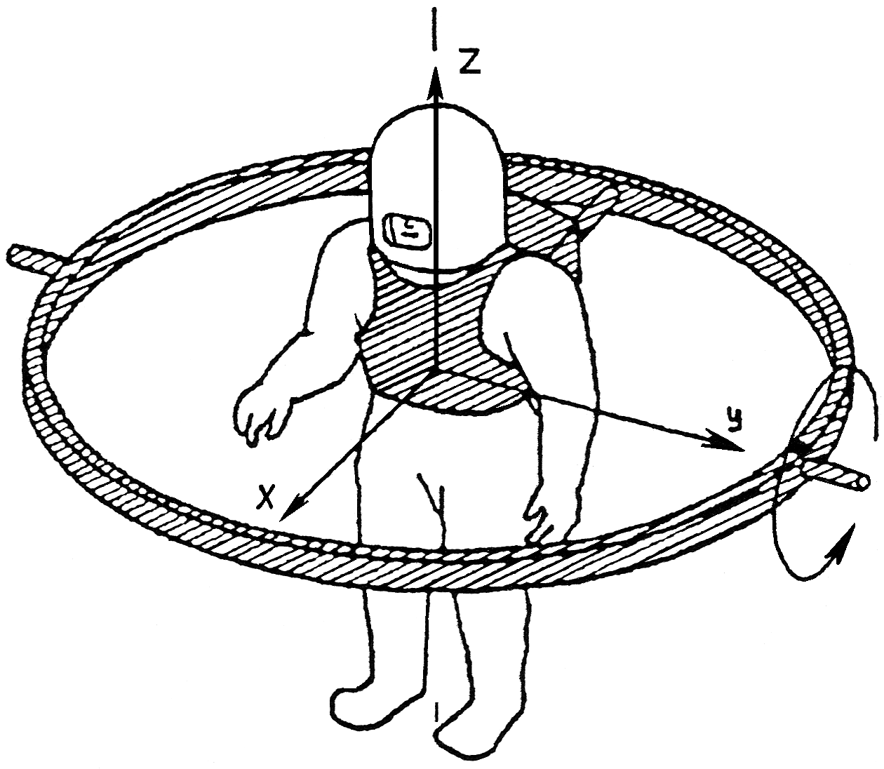
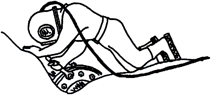
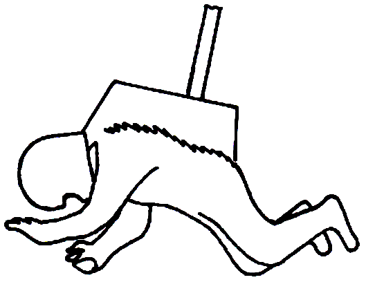
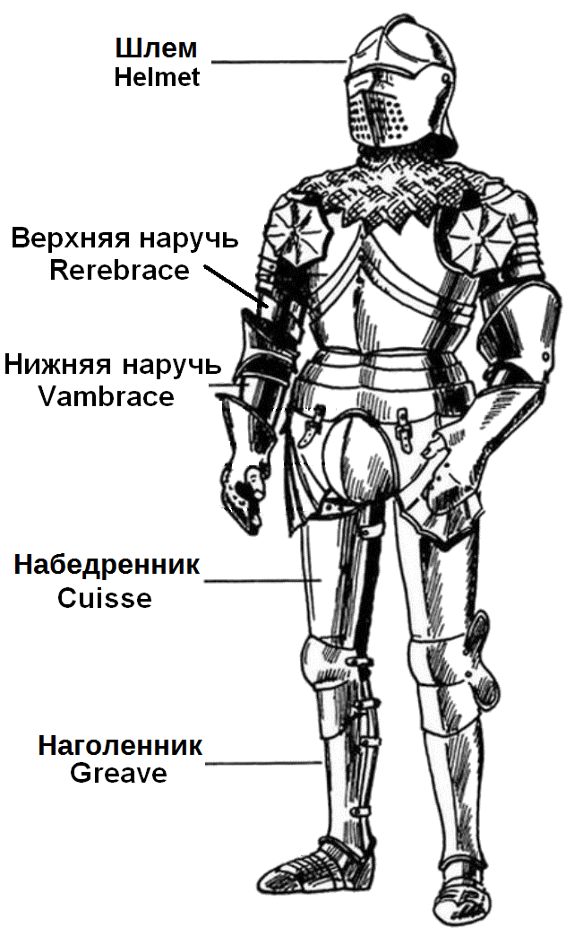


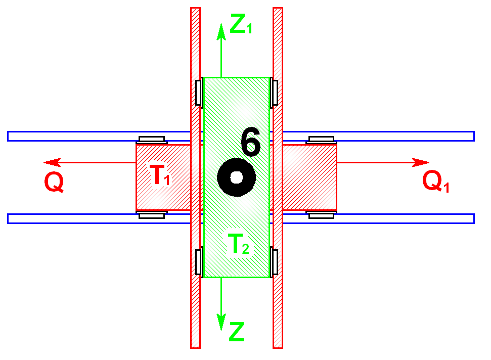
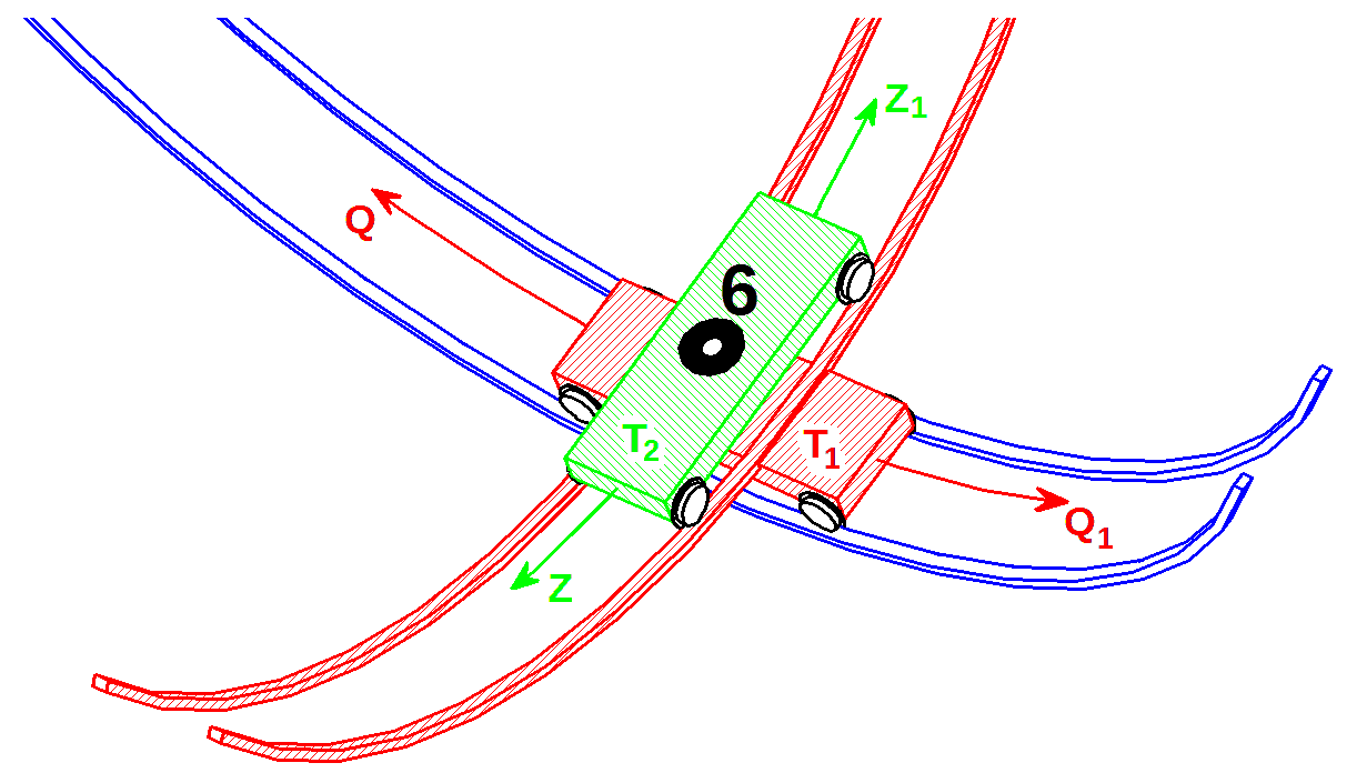
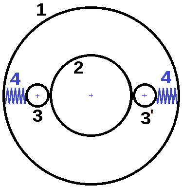
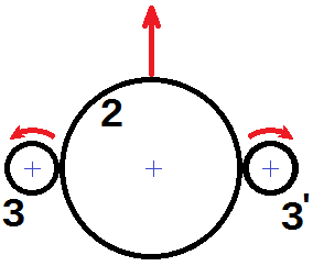
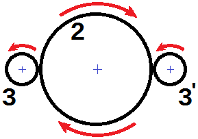
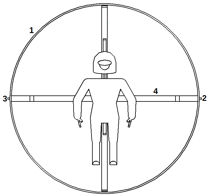
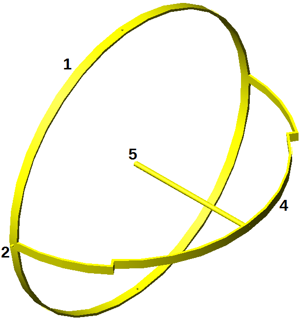

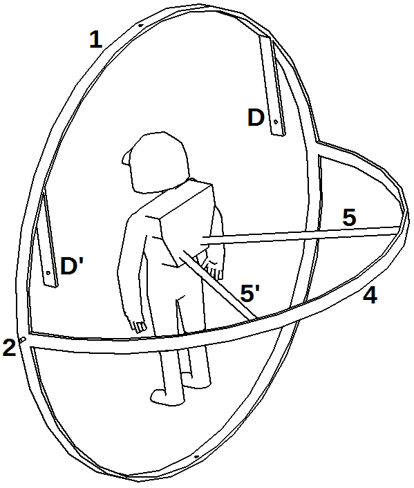
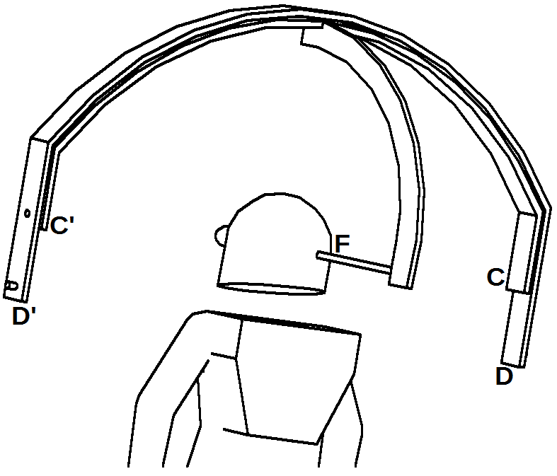
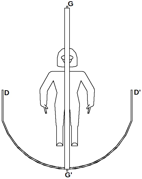


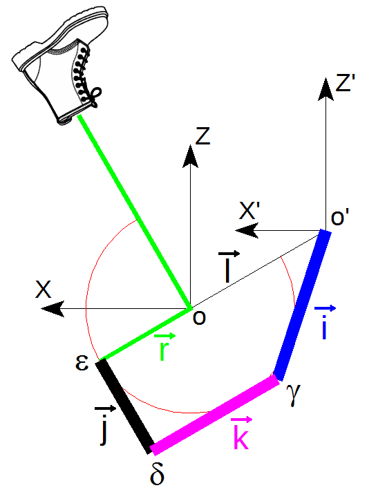
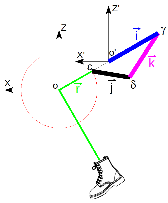
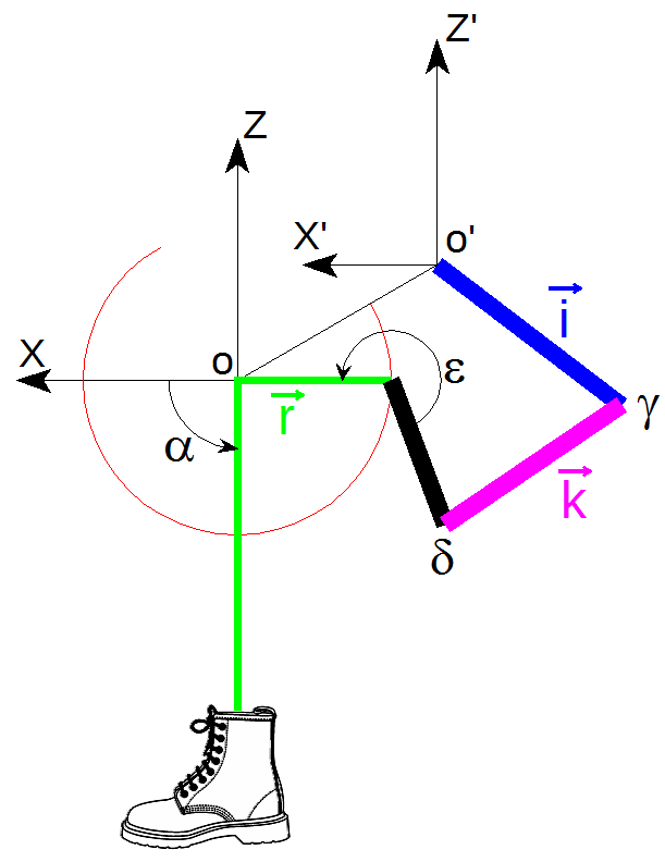
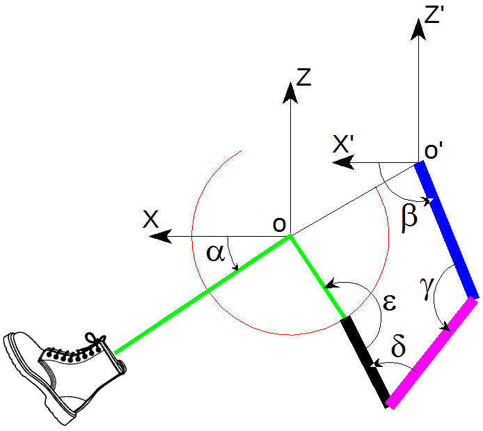
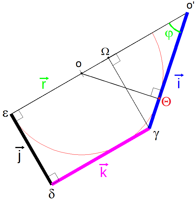
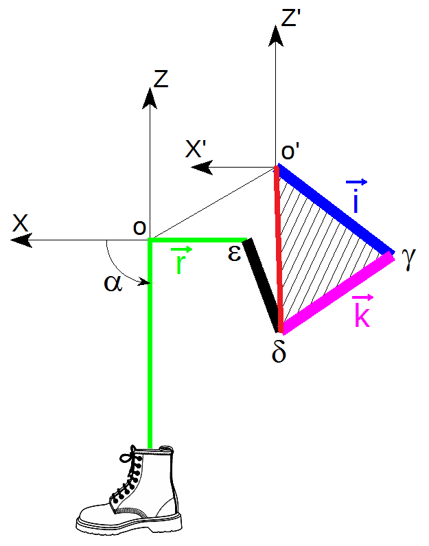


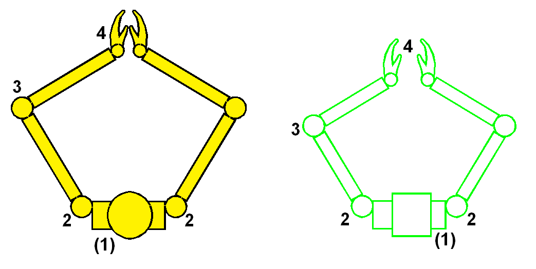

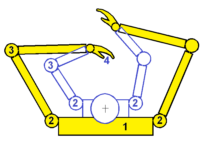
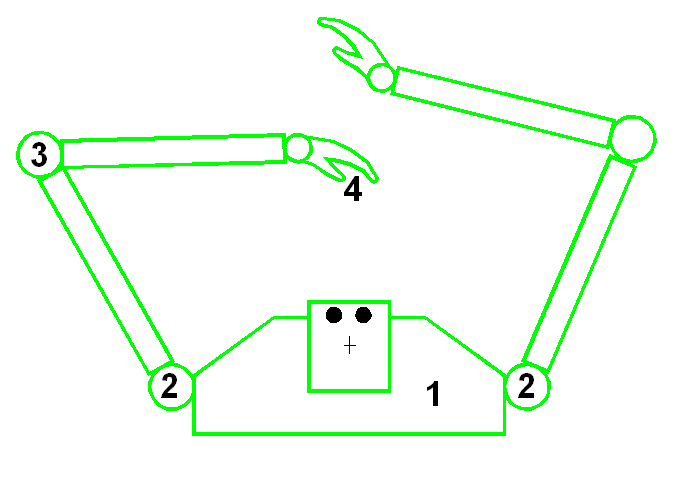


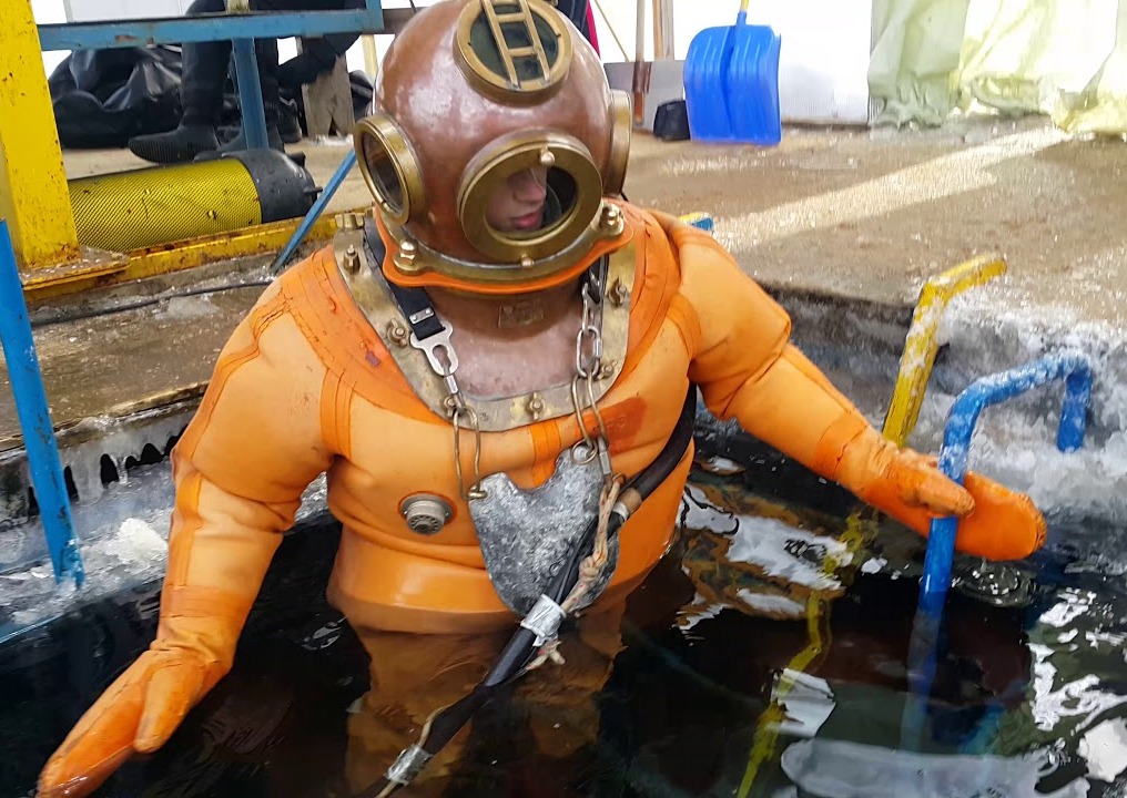
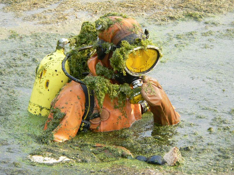
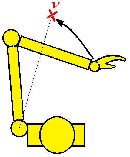
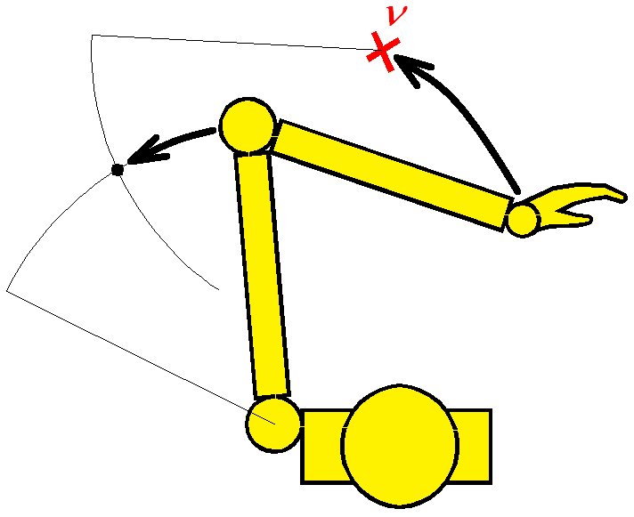
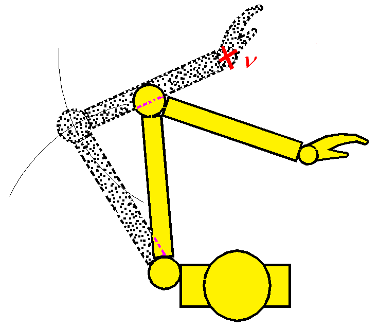
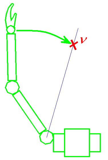
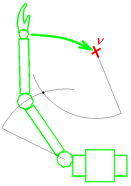
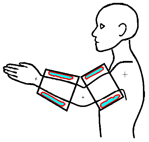
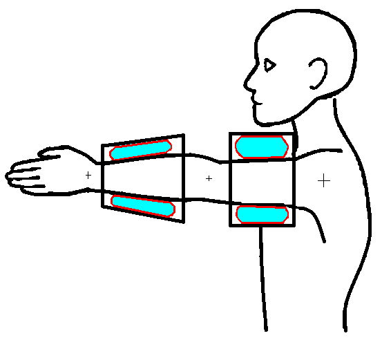
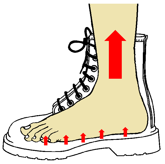

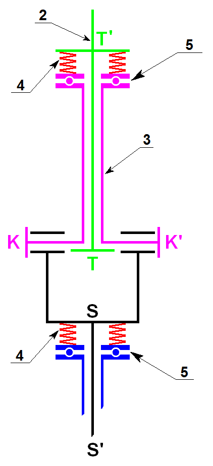
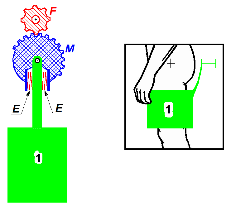
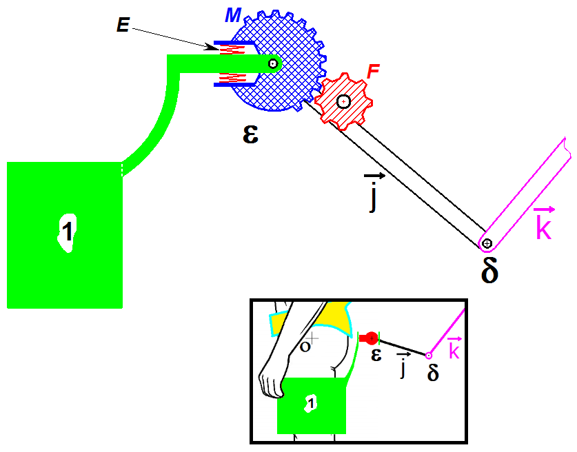
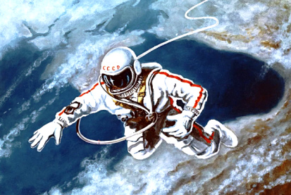

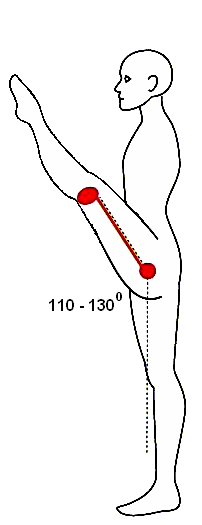
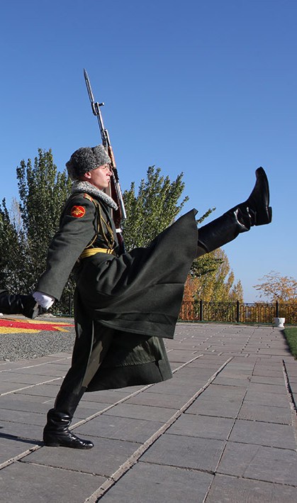


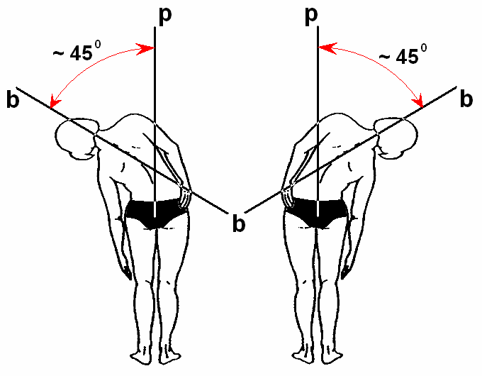
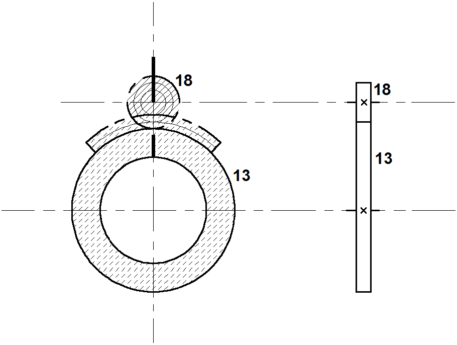
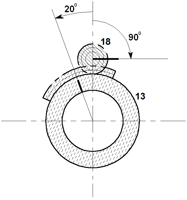
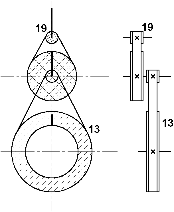
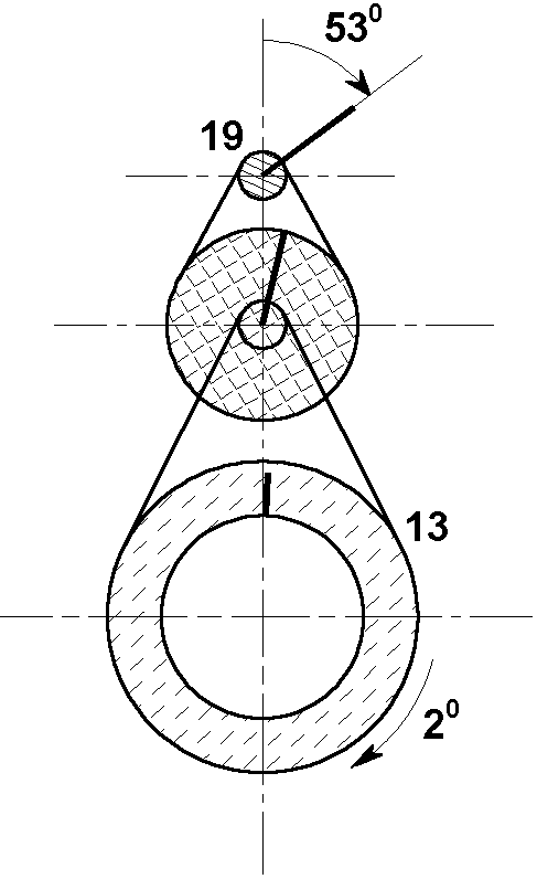
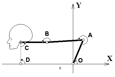
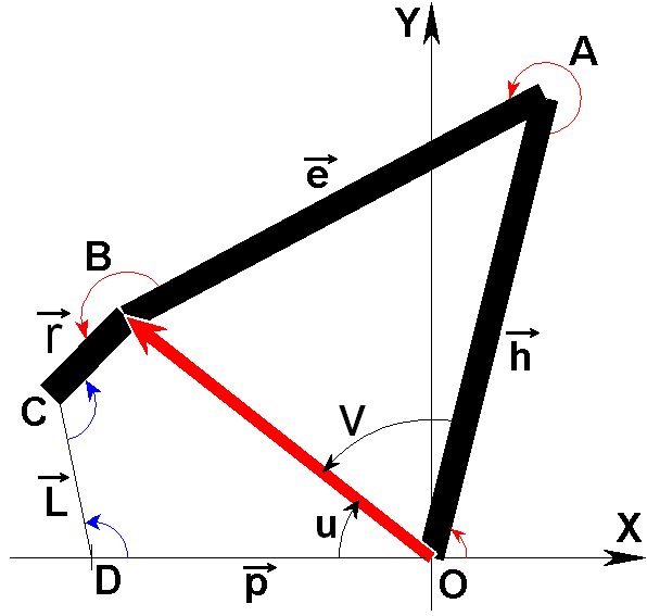
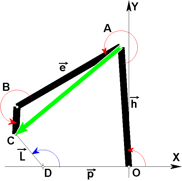
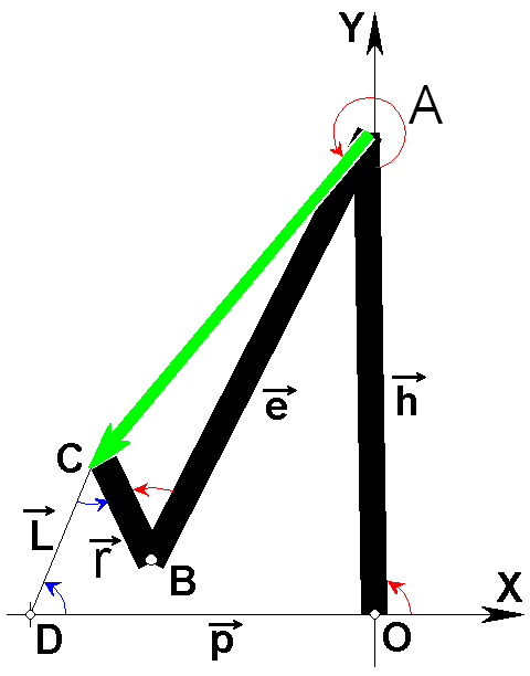
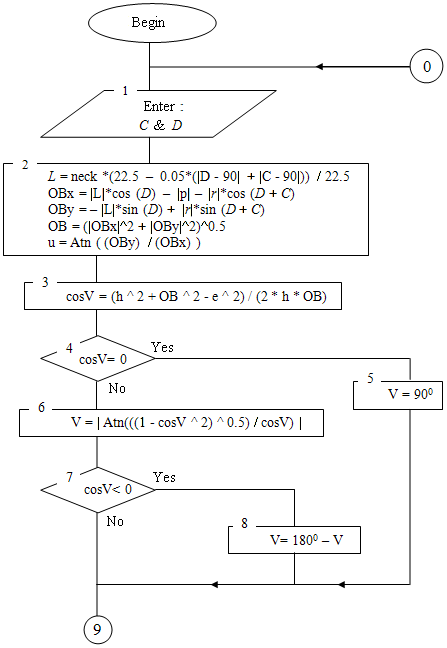
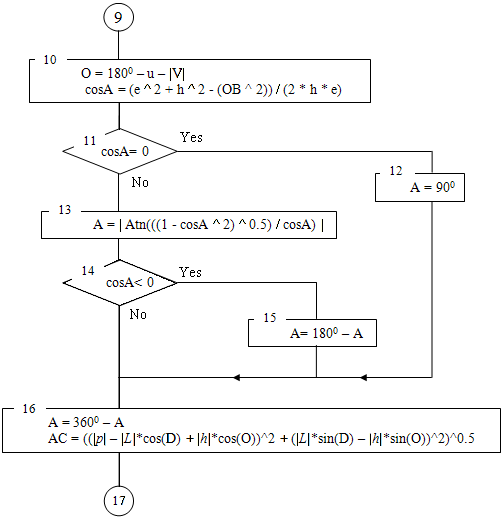
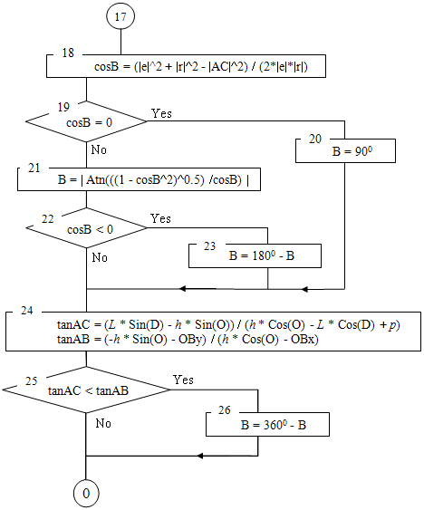


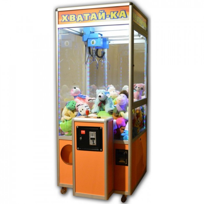
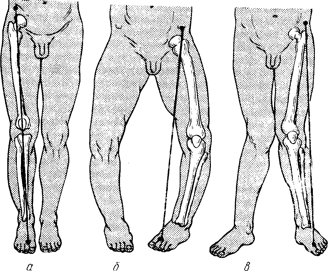
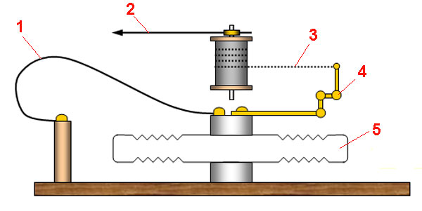
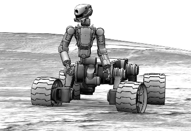